High-pass filter: principles, types, and practical uses
An overview of high-pass filters—circuits and algorithms that pass signals above a cutoff frequency—covering characteristics, common designs, applications, and design trade-offs.
Overview: A high-pass filter is a circuit or digital algorithm that allows frequencies above a specified cutoff to pass while attenuating lower-frequency components. Engineers use high-pass filters to remove DC offsets, rumble, and slow trends from signals, or to isolate higher-frequency content for further processing. The cutoff frequency defines the boundary between the passband and the stopband.
Image gallery
3 Images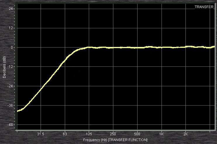

Key characteristics
Important attributes include cutoff frequency (often defined at the −3 dB point), slope or roll-off (commonly 20 dB/decade or 6 dB/octave per pole), phase response, and whether the filter is passive or active. A simple passive high-pass can be built with a series capacitor and a shunt resistor (an RC filter), where the cutoff fc = 1/(2πRC). Active implementations use op amps to provide gain and buffering.
Types and implementations
- Analog passive: RC and RL networks—simple, no power required, but limited gain and impedance effects.
- Analog active: Op-amp based first- and higher-order designs—allow selectable gain and lower source loading.
- Digital: FIR and IIR filters implemented in software or DSP—allow precise control of amplitude and phase, linear-phase FIR designs are common for minimal phase distortion.
Applications and examples
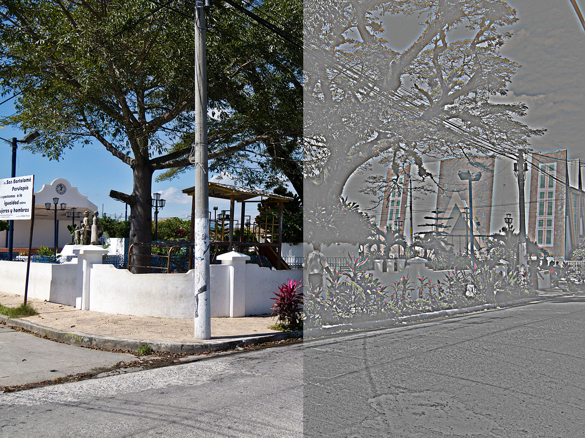
High-pass filters are widely used in audio (removing low-frequency rumble and DC), radio and communications (rejecting baseband noise), image processing (edge enhancement by removing slow spatial variations), instrumentation (eliminating sensor drift), and seismology (isolating higher-frequency seismic events). Practical designs balance cutoff choice, filter order, and acceptable phase distortion.
For practical design notes and step-by-step examples consult introductory resources such as high-pass basics, articles on cutoff frequency selection, and advanced material about numerical methods and windowed designs at filter design methods. These references discuss trade-offs like ripple, transient response, and computational cost.
Notable distinctions: A high-pass differs from a band-pass (which only passes a limited band) and a low-pass (which passes low frequencies). Designers must consider input/output impedance, component tolerances in analog filters, and stability and phase in digital implementations when choosing a suitable topology.
Related articles
Author
AlegsaOnline.com High-pass filter: principles, types, and practical uses Leandro Alegsa
URL: https://en.alegsaonline.com/art/44108