
Audio crossover: separating frequencies for loudspeaker systems
An audio crossover divides a full-range signal into frequency bands for different speaker drivers. Covers passive vs active designs, common components, filter slopes, history, practical uses and design considerations.
Overview
An audio crossover is an electrical filter network that splits an audio signal into two or more frequency ranges so that each range is sent to the speaker driver best suited to reproduce it. Crossovers protect small drivers from damaging low frequencies and prevent large drivers from attempting to reproduce high frequencies they are not designed to handle. Typical driver roles are the small loudspeaker, the tweeter for high tones, and the subwoofer for the lowest bass.
Image gallery
5 Images


Types and main components
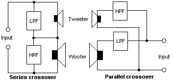
There are two broad categories of crossovers: passive and active. Passive crossovers are built from capacitors, inductors and resistors and are placed between an amplifier and the speaker. Active crossovers operate at line level before power amplification and commonly use op‑amps, transistors or digital signal processors. Passive parts are often simple LC or RC networks, while active systems can implement complex filters without the large, heavy components required for high-power passive stages.
- Common passive parts: capacitors, inductors, resistors.
- Typical active elements: op‑amps, active filters, and DSP modules. These generally draw power from a supply but do not dissipate as much signal power as passive resistors.
- Attenuation or level control: resistive pads or voltage dividers used to balance driver loudness (loudness pads).
Filter orders, slopes and alignments
Crossovers are characterized by their cutoff frequencies and the steepness of their rolloff, often expressed in decibels per octave. A first‑order filter rolls off at about 6 dB per octave, a second‑order at roughly 12 dB per octave, and higher orders provide steeper attenuation. Designers also choose alignments such as Butterworth or Linkwitz‑Riley to control amplitude and phase behavior at the crossover point, which affects how smoothly two drivers combine audibly.
History and technological development
Early speaker systems used simple passive networks to protect drivers and shape the response. As electronics progressed, active crossovers using transistor and op‑amp circuits became common in pro audio and studio applications because they allow precise control of crossover points and slopes. In recent decades digital crossovers implemented with DSPs have grown popular, offering flexible, recallable filter settings and advanced features such as time delay and phase correction.
Practical uses and examples
Crossovers are used in home hi‑fi speakers, car audio, public address systems and professional sound reinforcement. A typical two‑way home speaker will cross between woofer and tweeter in the range of a few kilohertz, while multiway professional systems add dedicated mid drivers and subwoofers with lower crossover points. In studio monitors and active speakers, built‑in active crossovers and amplification per driver are common to maximize control and efficiency.
Design considerations and notable distinctions
Choosing between passive and active designs depends on factors such as power handling, cost, space and desired adjustability. Passive crossovers are convenient and require no extra amplifiers, but high-power passive designs need large inductors and capacitors and can dissipate energy as heat. Active crossovers require separate amplifier channels for each driver but allow accurate, adjustable filtering and can incorporate features like equalization and delay. Proper speaker impedance, driver response and enclosure interaction must be considered to achieve coherent sound. For more technical background on passive networks see passive crossovers, and for practical advice and product examples consult manufacturer resources and application notes available at capacitor selection guides or electronics references linked from inductor and resistor component pages.
Further reading
For deeper study, explore topics such as crossover simulation, phase alignment techniques, FIR vs IIR digital filters, and recommended crossover frequency ranges for specific driver sizes. Manufacturer datasheets and professional audio textbooks provide practical guidance for matching crossover design to drivers and enclosures, while online forums and tutorials demonstrate real‑world implementations and troubleshooting tips (speaker design resources).
Related articles
Author
AlegsaOnline.com Audio crossover: separating frequencies for loudspeaker systems Leandro Alegsa
URL: https://en.alegsaonline.com/art/7243