Loudspeaker
![]()
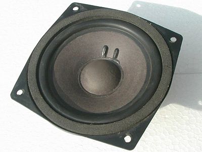
This article deals with individual loudspeakers (see picture) as technical components. For the hi-fi speakers used for sound reproduction in stereo or home cinema systems, see also speaker cabinet.
Loudspeakers ( ![]() ) are sound transducers that convert a (usually electrical) input signal into mechanical vibrations, perceptible as sound.
) are sound transducers that convert a (usually electrical) input signal into mechanical vibrations, perceptible as sound.
They are mostly used for the reproduction of speech and music with a typical operating range at frequencies from 20 to 50 Hz to 20 kHz, i.e. the human hearing range.
Special designs use the inverse piezo effect to generate sonar signals under water or ultrasound (piezo loudspeakers in animal scares, distance measuring devices, distance warning devices).
In the 1970s there were also ultrasonic remote controls.
For transducers that generate pulses or ultrasound in solids or in liquids, see also ultrasonic probe.
The size varies from very small shapes, used for example in in-ear headphones, to columns several meters high for sound reinforcement at large concerts.
The term loudspeaker is used inconsistently for the individual "loudspeaker chassis" or the "loudspeaker driver" as well as for the overall construction of the sound transducer built into a cabinet, which is also called loudspeaker cabinet.
The chassis, on the other hand, in the narrower sense only includes the immovable parts of a loudspeaker, while a driver is often only understood as the sound-converting part of a horn loudspeaker; this can easily lead to confusion.
Speakers that sit directly on the ears are called headphones.

Dynamic loudspeaker (plunger coil principle) with paper cone and rubber surround
History
→ Main article: History of the loudspeaker
The development of the loudspeaker is directly linked to the invention of the telephone and began in 1860 with the first public demonstration of a telephone set by Antonio Meucci. A year later, Philipp Reis presented his telephone, which was later further developed by Alexander Graham Bell.
Following Thomas Alva Edison's patent application for the phonograph in 1877, Emil Berliner presented his gramophone in 1887. However, its distinctive bell was not yet a loudspeaker in the sense of a "transducer" in that it merely emitted the mechanical vibrations of the needle through an acoustic horn.
Werner von Siemens received the patent for an electrodynamic loudspeaker as early as 1878; his misfortune, however, was the lack of suitable amplifiers. Sir Oliver Lodge is considered the founder of modern loudspeakers. At the Berlin Radio Exhibition in 1925, the first electrodynamically driven loudspeaker was presented to the public. In the same year, Edward Kellog and Chester Rice of the American company Western Electric had developed the dynamic moving-coil loudspeaker, as it is in principle still used today in most sound-emitting systems.
In addition to continuous optimization of the materials used, it was later above all the recording of the individual physical quantities that made it possible to improve the classic loudspeaker in a targeted manner - especially taking into account its interactions with the respective housing. At the same time, new forms of converting electrical impulses into sound were developed, including the vibration excitation of air plasma.
Loudspeaker boxes

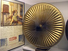
Magnetic loudspeaker of the Celestion company from the year 1924
Operating principle
General
In most cases, a loudspeaker consists of three groups of components: the diaphragm, the drive unit and their connecting elements. In the standard model of the so-called moving coil loudspeaker, the diaphragm is set in motion by a centrally mounted voice coil; in addition to the coil, the drive unit includes a magnet in whose field it vibrates. A basket connects the magnet to a surround and a spider, which in turn guide the diaphragm.
Depending on the application, the required volume, the frequency range, the available space and the desired signal fidelity determine how the transducer is designed in each case: Loudspeakers for announcements at the airport have to meet completely different requirements than player earphones or ultrasonic cleaners, for example.
In hi-fi loudspeaker cabinets, several frequency-specifically optimized transducers selectively controlled via loudspeaker crossovers are usually used to cover the entire listening spectrum. Loudspeakers can be described in their lower operating range by their Thiele-Small parameters, which makes the complex interaction of their components computationally tangible.
Membrane
Depending on the design and frequency, the diaphragm moves in a piston-like or wave-like manner. While bending wave transducers, for example, make use of the deformation effect, partial oscillations represent undesirable interference components in most loudspeakers.
To increase their stiffness, centrally driven diaphragms can be made funnel-shaped (which gives the usual cone speakers their appearance) and the most stable material possible can be chosen. However, hard materials such as aluminium or ceramics have pronounced natural resonances, while plastics such as polypropylene have good internal damping but weaken in terms of precision and efficiency. Today, a wide variety of mixtures and coatings are used; paper - already used for decades for loudspeaker cones - still delivers the best results.
To avoid partial vibrations, the diaphragm can also be driven over as large an area as possible. This principle is followed, for example, by magnetostats in which the voice coil - applied like a foil - is distributed over the entire diaphragm surface; its material may then be correspondingly thin (i.e. light and thus fast-pulse). However, the excursion of such surfaces is limited by the surrounding magnetic rods.
The lower the tone, i.e. the lower the frequency, the more air a diaphragm has to displace for the same volume. This volume results from the total area and the excursion capacity. Larger diaphragms are correspondingly heavier and more sluggish; in addition, sound bundling increases. In turn, greater excursion causes a higher mechanical load and requires a more complex drive.
Drive
The parameters of the drive depend both on the size of the coil (diameter and winding height) and on the strength and range of the magnetic field. The internal resistance of the coil (depending on the conductivity of its material), the distance between the coil and the magnet and any losses due to eddy currents (depending on the - undesirable - conductivity of the coil carrier) are also decisive.
The use of new materials such as neodymium has made it possible to produce much stronger magnets than was possible at the beginning of loudspeaker development. Apart from the obvious advantages, a more powerful drive alone does not necessarily result in an "improvement" of the loudspeaker; in the case of a built-in woofer, the required cabinet volume is reduced, but at the same time the lower cut-off frequency increases.
With piezo speakers, there is no coil or magnet: The signal is applied to a disc of piezoelectric material that is directly connected to the diaphragm. Electrostats, on the other hand, work with a highly transformed signal that acts via stators on a foil membrane under constant voltage; in the plasma loudspeaker, an ionized gas is set in vibration with a high-voltage field.
Basics theory
In the lower operating range around the resonant frequency, loudspeakers operating as a driven mass-spring system can be described by the Thiele-Small parameters.
Similar to electric current, which can be described by the electric current intensity and the electric voltage, sound waves have the sound velocity and the sound (change) pressure. Sound velocity describes the speed with which the air molecules are moved by the sound, while sound pressure describes the resulting pressure. Due to the low sound impedance of air, the sound radiation of a membrane to the surrounding air is very inefficient. At low frequencies it drops further to 0, at higher frequencies it rises with some overshoots up to a limit given by the shape and size of the membrane. In the classic problem of the piston radiator in an infinite baffle in an infinite space on all sides, the radiation resistance up to the limit is proportional to the frequency. This should result in a sound image with a strong emphasis on high frequencies. However, it is the case with almost all radiators that the applied mechanical force is constant for higher frequencies and therefore, according to Newton, so is the acceleration. This means that the velocity is inversely proportional to the frequency. This exactly compensates for the increase in radiation resistance. In most radiators, therefore, there is, without further ado, a range in which the radiated power is independent of the frequency, and this is consequently chosen as the main working range.
The example with the infinite baffle shows that an analytical mathematical treatment is only possible in simple model cases. Several membranes or resonators interact with each other and with the structural elements of rooms. Among other things, this changes the radiation resistance. The radiation resistance can be thought of as a summarized reaction of the radiation field on the radiator.
In the case of direct radiators consisting only of membranes, the forces with which the radiation field acts back on the membrane are negligible compared to the driving force, the mass inertia and the elastic spring forces. The movement of the diaphragm is thus practically independent of the barometric equal air pressure, up to vacuum. Electrical and mechanical measurements on drivers in the free field are thus comparable to those in the reverberation chamber. The calculation of the interconnection of several diaphragms to form a field can therefore be made by simple, feedback-free superposition of the individual characteristics. In this case one speaks of a mismatch with correspondingly low efficiency.
The use of acoustic resonators or impedance transformers, for example horns, changes the coupling of the diaphragm to the radiation field very drastically in narrow or wide bands. The forces of the radiation field on the diaphragm are no longer negligible. In this case, the interconnection is not free of feedback and the other simplifications no longer apply either. In this case, one speaks of power matching with good efficiency.

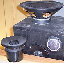
Examples for HiFi-speakers: a box (black, only partly visible, with built-in tweeter and midrange speaker), on top of it a removed woofer, in front on the wooden panel a removed midrange speaker
Search within the encyclopedia