
Capacitor: function, construction, history, types and common uses
A capacitor is an electrical component that stores energy in an electric field. This article explains how capacitors work, common constructions and types, history, applications, specifications and safety guidance.
A capacitor is a passive electrical component that stores energy electrostatically in an electric field formed between two conductors separated by an insulating layer (the dielectric). Capacitors are used throughout electronics and electrical systems to shape signals, smooth power, provide short bursts of energy and affect circuit timing. Early devices such as the Leyden jar demonstrated basic charge storage and led to the modern range of capacitor types used today.
Image gallery
10 Images
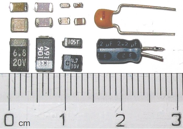


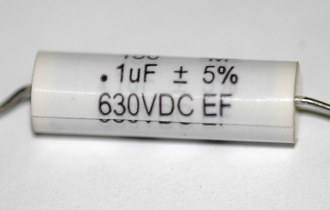


Basic structure and how capacitors work
Typical capacitors consist of two conductive plates or foils placed near one another but insulated by a dielectric such as ceramic, plastic film, mica, paper, glass or a liquid electrolyte. When a voltage is applied, equal and opposite charges accumulate on the two plates and an electric field forms across the dielectric. The ability to store charge per unit voltage is the device's capacitance, measured in farads. Practical values used in circuits are usually much smaller than a farad and are quoted in common submultiples.
Construction, shapes and materials
To increase plate area and thus capacitance in a compact volume, foil and dielectric layers are often rolled into a cylindrical form or stacked in multiple layers. Surface-mount multilayer ceramic capacitors stack alternating metal and dielectric layers to achieve useful capacitance in tiny packages—some as small as an ant in apparent size. Electrolytic capacitors use a chemically formed dielectric and an electrolyte to obtain higher capacitance per volume; film, mica and glass types emphasize stability and low loss.
Common types and special varieties
- Ceramic — widely used for decoupling and filtering because they are small and nonpolar.
- Electrolytic — higher capacitance density, typically polarized and used for bulk energy storage on power rails.
- Film — reliable and stable for timing, audio and power applications.
- Tantalum and polymer — types of electrolytic capacitors offering specific performance trade-offs.
- Supercapacitors — provide very large capacitance values for short-term energy buffering between conventional capacitors and batteries.
- Variable and trimmer capacitors — adjustable units for tuning radios and calibration.
Electrical characteristics and specifications
Important specifications include capacitance value, maximum working voltage, tolerance, leakage current, equivalent series resistance (ESR) and temperature stability. ESR and internal inductance influence performance at high frequency. Capacitor datasheets and application notes explain how these parameters affect ripple handling, timing accuracy and lifetime for a given application.
Applications
Capacitors are versatile: they filter and smooth power supplies, block direct current while passing alternating current in coupling applications, form timing elements in oscillators and filters, and store energy for brief, high-power needs. Devices that exploit rapid discharge include photographic flash circuits and medical defibrillators: a charged capacitor can deliver a large pulse of energy when required, which is why a photoflash and a defibrillator both rely on capacitors to provide short, intense bursts of power.
Practical considerations and safety
Some capacitors are polarized and must be installed with correct polarity; reverse voltage can damage the device or cause violent failure in electrolytic types. Large capacitors can retain a hazardous charge long after power is removed, so safe discharge procedures are essential. Designers also manage parasitic or stray capacitance: any two conductors separated by an insulator exhibit capacitance, which can affect sensitive circuits or be exploited intentionally. Understanding how a capacitor compares to an electrochemical battery helps select the right component for energy storage versus sustained power delivery.
Selection, measurement and design tips
Select capacitors based on the electrical environment: choose low-ESR parts for high ripple currents, capacitors with appropriate temperature coefficients where stability matters, and high-voltage-rated parts when transients are present. Measurement of capacitance, ESR and leakage can be done with common test instruments. Practical layout techniques reduce unwanted coupling and maintain predictable performance in analog and high-frequency digital circuits.
History, development and further reading
The development from the Leyden jar to modern multilayer and electrolytic capacitors reflects advances in materials and manufacturing. For basic theory and component selection guides consult introductory texts and manufacturer application notes; for component sourcing and specifications, compare datasheets and use trusted component libraries. For an accessible introduction to capacitor principles see a basic capacitor overview and, for effects of nearby conductors, read about parasitic capacitance.
This article summarizes common knowledge about capacitors, their roles in circuits, construction approaches and safety practices. For practical projects start with common ceramic or film capacitors and review manufacturer guidance before working with high-voltage or large-capacitance devices.

How it works
A capacitor blocks the direct current but passes on the alternating current.
Functionality in the DC circuit
After applying a DC voltage to a real capacitor with series resistor, a monotonic electric current flows which charges the electrodes with opposite polarity, so that a constantly increasing voltage builds up in the capacitor. The electric potential building up on the electrodes causes an electric field to develop in the space between the electrodes, the field strength of which is proportional to the voltage built up.
In the case of a DC voltage source with constant internal resistance, the voltage at the capacitor here follows an exponential function with a negative exponent, so that the current asymptotically approaches zero over time. If the voltage source and capacitor have the same voltage, then no current flows ("the capacitor is charged").
When the capacitor is disconnected from the voltage source, the energy and charges are conserved and the voltage remains constant. In general terms, this means that the charge on the electrodes is stored by the capacitor. If energy is taken from the capacitor by connecting a load, then the field strength of the electric field decreases and so does the capacitor voltage.
Since in a closed circuit the current flows throughout the circuit, it also flows through the capacitor. Physically, however, the current in the circuit consists of two currents, a conducted current of charge carriers such as electrons or ions and a so-called displacement current in the space between the electrodes, which is to be understood as part of the effect of the electric field and is accompanied by a corresponding change in electric field strength. In real capacitors, the space between the electrodes is filled with a dielectric. The displacement current then results, in addition to the part due to the change in field strength, from the charge displacement in the dielectric, the polarization, which results from its dielectric constant.
For small field strengths and linear dielectric materials, the polarization grows linearly with the voltage across the capacitor. The charge stored in the capacitor grows proportionally to the voltage. The constant of proportionality is called capacitance; it is the essential characteristic of a capacitor. The larger the capacitance  , the more charge
  and energy a capacitor can
 store at a given voltage The equations

respectively

and

summarize that. is the charge (in coulombs, C, or ampere-seconds, As), is the capacitance (in farads, F), and is the voltage (in volts, V); the energy (in joules, J) is denoted distinguish it from the field strength . 
Real capacitors can only be charged up to a maximum permissible voltage, which results from the dielectric strength of the dielectric.
The time a real capacitor needs to charge up or to be discharged can be taken from the article RC element.
Functionality in the alternating current circuit
Capacitors pass on alternating voltages and alternating currents in the alternating current circuit, but with a shift in the phase position between voltage and current; the current precedes the voltage by 90°. This is because, due to their charge storage capability, a current begins to flow in capacitors before the voltage changes, whereas in an inductor the voltage changes before a current flows. Mnemotechnics:
- At the capacitor: current rushes ahead.
- For inductors: currents are delayed.
A capacitor with capacitance (F) forms an AC resistance in the AC circuit at the angular frequency ω  as a quotient of the AC voltage
  and the AC current
  with the impedance
  (Ω) as a complex quantity:
 .
.
The magnitude of the complex impedance is the impedance  .
.
The impedance is smaller the larger the capacitance and the higher the frequency.
The property of capacitors as AC resistors with the lowest possible impedance is used not only for energy storage but also in many applications for the separation of DC and AC components, for the correction of phase shifts and for the generation of resonant circuits. The discharge differential equation, which is important for many applications, can be found in the article RC element.


History
Leyden jar
→ Main article: Leyden bottle
The Leiden flask is the oldest type of capacitor (capacity about 5 nF). It consists of a glass vessel covered inside and outside with metal foil, usually aluminium. The glass acts as an insulator, later called "dielectric". The principle of the Leiden bottle was found independently in 1745 by the cathedral dean Ewald Jürgen Georg von Kleist in Cammin (Pomerania) and a year later by the physicist Pieter van Musschenbroek in Leiden, when they suffered electric shocks during laboratory experiments with arrangements of glasses and metal parts.
The Leiden flask and similar laboratory devices were subsequently used primarily for public demonstrations of electric shocks (also known as "Kleist's shock"), and later, as knowledge of the nature of electricity increased, as a source of energy for more advanced experiments: Benjamin Franklin connected a Leyden jar via a metal cord to a kite, which he launched into the sky. With this dangerous experiment, he succeeded in transferring charge from thunderclouds to the Leyden jar. He coined the term "electrical condenser".
Further development
An improved capacitor was invented in 1775 by Alessandro Volta (1745-1827), who called it "electrophorus" (electrophore, carrier of electricity). It consisted of two metal plates insulated from each other by a layer of ebonite. This arrangement can already be considered the prototype of modern capacitors. The use of better dielectrics later led to a reduction in size. Around 1850, mica, a naturally occurring mineral, was sliced and used as an insulator; commercially, these capacitors were produced from the time of World War I onwards. Wound paper capacitors with metal foil facings have been in use since 1876.
Capacitors that resulted in capacitors with higher capacitance through the chemical construction of an extremely thin dielectric of non-conductive aluminium oxide on an aluminium anode and the use of a liquid electrolyte, the later "electrolytic capacitors", were patented in 1896 by Charles Pollak. They were initially used as filter capacitors to suppress humming noises in telephone networks.
Since about 1900, porcelain was also used as a dielectric in capacitors. It was not until the 1930s that the development of ceramic capacitors took place as a result of research into other ceramic materials to replace porcelain and mica.
Mica as a dielectric in capacitors was first used by William Dubilier in the USA in 1909 and was the most widely used material for capacitors in communications equipment until the outbreak of World War II. Nowadays, mica capacitors have been replaced by improved class 1 ceramic capacitors.
With the development of high quality insulating plastic films from the field of organic chemistry after World War II, the industry began to replace the paper in metal-paper capacitors with thinner and more voltage-resistant plastic films, which evolved into a wide range of different plastic film capacitors.
From around 1950, General Electric in the USA began developing tantalum electrolytic capacitors. Here, it was not only possible to achieve miniaturization through a considerably higher capacity per construction volume compared to the previously known capacitors, but with the development of a solid electrolyte, the long-term stability of electrolytic capacitors could also be significantly improved.
Another significant increase in capacitance was achieved with the "low voltage electrolytic capacitor" patented by General Electric in 1957, which was further developed into a marketable component by SOHIO and, from 1971, by NEC, and initially received the designation "double-layer capacitor", which now became the designation supercapacitor due to the findings on pseudocapacitance.
Silicon capacitors are a more recent development. These result from the semiconductor industry's extensive experience with structuring silicon and offer the user frequency-stable capacitance values up into the gigahertz range.
In recent years, there has been a development in all suitable capacitor types towards ever smaller construction volumes and surface-mountable (SMD) capacitors. In addition, a considerable increase in electrolyte conductivity and correspondingly lower loss resistances have been achieved, especially for aluminum and tantalum electrolytic capacitors, through the introduction of new polymer electrolyte systems.
Current (2009) research is concerned, among other things, with new surface structuring of the electrodes. For example, a nanostructure in the form of billions of small holes next to each other in a thin aluminium layer, coated with titanium nitride/aluminium oxide/titanium nitride as a capacitive structure, can increase the power density of a nanocapacitor, measured in W/kg, by more than ten times compared to electrolytic capacitors and thus achieve a storage capacity in the order of magnitude of double-layer capacitors without exhibiting their disadvantage, the limited charging or discharging speed.
Another way to increase capacitance is to use better dielectrics. This is achieved, for example, by incorporating barium titanate into a non-conductive matrix, which results in a higher permittivity than with ceramic capacitors, while the dielectric remains robust and malleable as with film capacitors.
Market
Capacitors are found in almost all electrical and electronic equipment. According to the estimate of an industry report, in 2008 the value of all capacitors sold worldwide amounted to US$ 18 billion. Of this, ceramic capacitors accounted for US$8.3 billion (46%), aluminum electrolytic capacitors US$3.9 billion (22%), plastic film and metal paper capacitors US$2.6 billion (15%), tantalum electrolytic capacitors US$2.2 billion (12%), double layer and super capacitors US$0.3 billion (2%), and other capacitors such as vacuum capacitors US$0.7 billion (3%). In particular, the development in the field of new telecommunication devices and tablet computers with their MLCC chip capacitors has significantly driven the market. Of the approximately 1.4 trillion (1.4-1012) capacitors (2008), MLCC chips alone accounted for approximately 1 trillion (1.0-1012) units.
The market for industrially produced capacitors and those required by industry has declined somewhat in the following years, because in many cases more expensive capacitors have been replaced by cheaper solutions. For example, tantalum chips were replaced by MLCCs. The capacitor market was estimated at US$16.9 billion in 2016.


Questions and answers
Q: What is a capacitor?
A: A capacitor is an electronic device that stores electric energy. It is similar to a battery, but can be smaller and lighter, and charges or discharges much quicker.
Q: What was one of the first capacitors invented?
A: The Leyden jar was one of the first capacitors invented.
Q: How do capacitors store energy?
A: Capacitors store energy inside an electrical field created by two metal plates that are on top of each other and near each other, but that do not actually touch. Sometimes, other shapes of capacitors are used for special purposes. A capacitor-like effect can also result just from two conductors being close to each other, whether you want it to exist or not.
Q: What type of capacitor should be used depending on the application?
A: The type of capacitor used depends on the application. Capacitors come in many sizes and some are adjustable.
Q: How many connections does a capacitor have?
A: All capacitors have two connections, or leads.
Q: Is it easy to replace most kinds of capacitors?
A: Most kinds of capacitors can be replaced easily by someone who has basic skills in electronics. However, one of the more powerful types - the electrolytic capacitor - must be used correctly or they can explode violently.
Q: What makes a capacitor different from a battery?
A:Capacitor charges or discharges much quicker than batteries and they can release all their stored energy very quickly, even faster than a second whereas batteries take longer time to discharge their stored power
Related articles
Author
AlegsaOnline.com Capacitor: function, construction, history, types and common uses Leandro Alegsa
URL: https://en.alegsaonline.com/art/16689