
Rectifier: Converting Alternating Current to Direct Current
Overview of rectifiers: purpose, types (half-wave, full-wave, bridge), components, history, applications, and technical considerations such as ripple, smoothing, and controlled rectification.
A rectifier is an electrical device that converts alternating current into direct current, a process known as rectification. The basic purpose is to allow current to flow preferentially in one direction so that an AC waveform is turned into a unidirectional output. Early rectifiers used mechanical or metal contacts and vacuum tubes; modern designs are dominated by semiconductor devices such as diodes and controlled switches.
Image gallery
10 Images



Fundamental principles and components
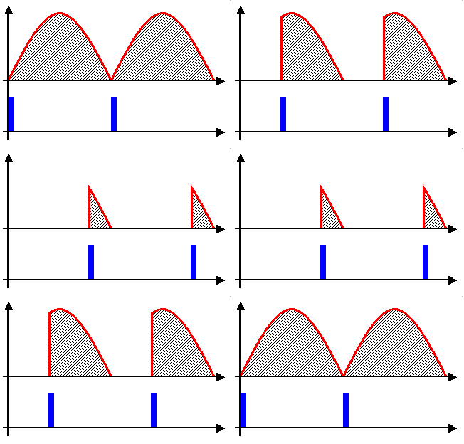
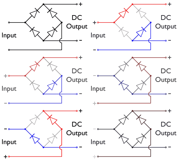
Rectification relies on non‑linear elements that conduct easily in one polarity and block in the opposite. The simplest such element is the semiconductor diode. A single diode permits half‑wave rectification: only the positive (or negative) half of the alternating waveform appears at the output. Full‑wave rectification uses the absolute value of the input waveform so both halves contribute to the output. Practical rectifier circuits commonly combine diodes into configurations such as a bridge made of four diodes to implement full‑wave rectification without a center‑tapped transformer.
Common rectifier topologies
- Half‑wave rectifier: one diode; simple but wastes half the input and produces high ripple.
- Full‑wave (center‑tap): two diodes and a center‑tapped transformer; uses both halves but requires special transformer winding.
- Bridge rectifier: four diodes in a bridge arrangement that produces full‑wave output without a center tap; widely used in power supplies.
- Controlled rectifiers: devices such as thyristors or silicon‑controlled rectifiers (SCRs) allow timing control of conduction for regulated DC or phase‑angle control.
History and technology evolution
Rectification methods evolved from metal and electrolytic rectifiers and vacuum tube rectifiers in the early 20th century to semiconductor diodes after the development of solid‑state technology. Modern rectifiers use silicon or silicon carbide diodes and controlled switches, offering higher efficiency, lower losses, and smaller size. Improvements in power electronics and semiconductor materials expanded rectifier use in industry and consumer electronics.
Applications and practical considerations
Rectifiers are a core element of power supplies for electronic equipment, battery chargers, DC motor drives, and high‑voltage DC transmission systems. The raw rectified output is pulsating DC and typically requires smoothing using capacitors, inductors, or active regulators to reduce ripple and maintain a steady voltage suitable for electronics. Ripple frequency depends on topology: full‑wave rectification doubles the ripple frequency compared with half‑wave, making filtering more effective.
Notable distinctions and related concepts
Rectification should be distinguished from regulation: rectifiers convert waveform polarity while regulators control voltage or current magnitude. Single‑phase and three‑phase rectifiers differ in complexity and ripple characteristics; three‑phase designs provide smoother DC with lower filtering demands. In modern systems, rectifiers are paired with inverters and converters in motor drives, renewable energy interfaces, and uninterruptible power supplies. For basic concepts see AC and DC, for semiconductor device introductions see semiconductor overviews, and for circuit examples see typical circuit diagrams.
Understanding rectifiers is essential in electronics and power engineering because they form the bridge between AC generation and the DC needs of most electronic devices.
Related articles
Author
AlegsaOnline.com Rectifier: Converting Alternating Current to Direct Current Leandro Alegsa
URL: https://en.alegsaonline.com/art/81607
Sources
- nd.edu : "What is a Rectifier Circuit?"
- wisc-online.com : "Half-Wave Rectifier"