Cross section (geometry)
A cross section is the intersection produced when a geometric object is cut by a line or plane; used in mathematics, engineering, and design to analyze shape, area, and internal structure.
Overview
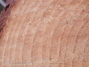
A cross section is the curve, polygon or region obtained when a geometric object is intersected by a lower-dimensional set. In elementary terms, it is what remains of an object after it is sliced. In geometry this idea is formalized: the intersection of a body in two-dimensional space with a line, or of a body in three-dimensional space with a plane, yields a cross section. Cross sections reveal internal structure and can simplify analysis by reducing dimensions.
Image gallery
4 Images
Definition and basic properties
Formally, a cross section is the intersection of a set S with a subspace of lower dimension. For a solid in three dimensions, a plane slice produces a two-dimensional region; for a plane figure, a line slice produces a one-dimensional segment or curve. Properties of the cross section (for example area, shape, and topology) depend on both the original object and the orientation and position of the cutting plane or line.
Types and typical examples
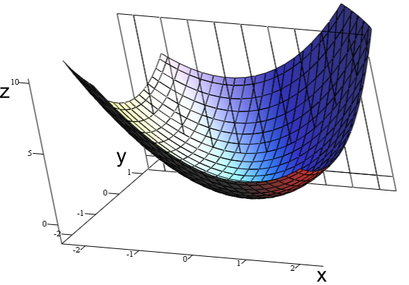
- Planar sections of solids: slicing a cylinder with a plane parallel to its axis gives a rectangle; slicing perpendicular to its axis gives a circle.
- Conic sections: intersections of a plane with a cone produce ellipses, parabolas, and hyperbolas—classical examples in analytic geometry.
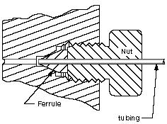
- Profile and elevation: architectural drawings use horizontal and vertical sections to show internal layouts and heights; a floor plan is a section viewed from above.
Construction methods
Cross sections can be obtained by analytical calculation, construction, or physical cutting. Analytically, one substitutes the equation of the slicing plane or line into the object’s equations and simplifies to find the curve or region. Practically, models are cut to produce tangible sections. In technical drawing the concept is closely related to orthographic projection and sectional views used to communicate interior details.
Applications and importance
Cross sections are central in many fields: computing areas and volumes in calculus, analyzing stress distributions in structural engineering, interpreting medical imaging (slices in CT or MRI), and creating technical drawings. An orthographic sectional view helps engineers and builders visualize hidden components; see orthographic projection and typical plans such as a floor plan.
Distinctions and notable facts
Different orientations of the cutting plane can produce dramatically different sections from the same object. While the term is often used interchangeably with "section," some disciplines distinguish a mathematical intersection from the representational sectional drawing used in drafting. For two-dimensional figures the analogous concept uses a line as the slicing instrument; for example, intersecting polygons with lines yields segmental cross sections and is treated within planar geometry and computational algorithms—see resources on 2D intersections and 3D plane intersections for further context.
Related articles
Author
AlegsaOnline.com Cross section (geometry) Leandro Alegsa
URL: https://en.alegsaonline.com/art/24332