Band-pass filter: function, types, and practical applications
A band-pass filter allows signals within a defined frequency range to pass while attenuating others. Covers principles, parameters (center, bandwidth, Q), types, history, and common uses in electronics and DSP.
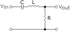
A band-pass filter is a circuit or algorithm that transmits components of a signal whose frequency lies between two specified limits while attenuating frequencies outside that interval. In practice a band-pass can be built from a cascade of a high-pass and a low-pass stage, or as a single resonant network tuned to a center frequency. Key descriptive parameters are the lower and upper cutoff frequencies, the bandwidth (difference between them) and the quality factor (Q), which relates center frequency to bandwidth.
Image gallery
2 Images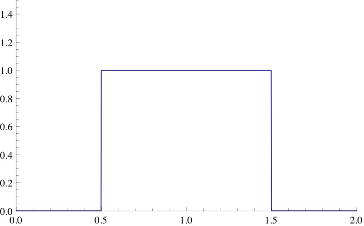
Basic characteristics and parameters
The most important numbers for a band-pass are the lower cutoff (f1), upper cutoff (f2), the center or resonant frequency (f0) and the bandwidth (BW = f2 − f1). A higher Q indicates a narrower passband for the same center frequency. Response shapes follow standard prototypes such as Butterworth, Chebyshev or elliptic designs, which trade flatness in the passband against roll-off steepness and ripple.
Types and implementations
- Passive filters: Built from resistors, capacitors and inductors; they require no power but cannot provide gain. At low frequencies (audio and below) RC networks are common; at radio frequencies RLC resonant circuits are typical.
- Active filters: Use amplifiers (op‑amps) or transistors together with RC networks to realize band-pass responses with gain and better control of Q.
- Digital filters: Implemented in software or programmable hardware, offering precise, reproducible band-pass behavior and flexibility for adaptive systems.
History and development
Band-pass filtering has roots in early radio and telecommunication engineering, where selecting a particular channel or frequency band was essential. The development of mathematical filter theory and standardized response types (e.g., Butterworth, Chebyshev) made it possible to design predictable analog filters; later advances in integrated circuits and digital signal processing broadened the range of practical implementations.
Applications and notable distinctions
Band-pass filters are used widely: in radio receivers to isolate a station, in audio systems for crossovers, in instrumentation to remove noise outside an interest band, and in optics where dielectric coatings pass a spectral band. They differ from band-stop (notch) filters, which remove a narrow range, and from simple low-pass or high-pass filters that permit frequencies below or above a single cutoff. Practical design choices often balance component cost, size, power, achievable Q and required stability.
For more technical details and component examples see an introductory reference on electronic filter design and a primer on cutoff definitions at lower and upper cutoff conventions.
Related articles
Author
AlegsaOnline.com Band-pass filter: function, types, and practical applications Leandro Alegsa
URL: https://en.alegsaonline.com/art/8674