
Bending (structural behavior)
Bending, or flexure, describes how structural elements deform under transverse loads, governing stresses, deflections, and design criteria for beams in engineering and mechanics.
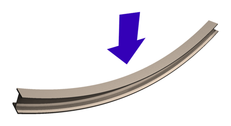
For other senses of the word see Bending (disambiguation). In the context of engineering and structural mechanics, bending (also called flexure) refers to the deformation of an element when it is subjected to a lateral or transverse load applied at approximately right angles to its longitudinal axis. It is one of the fundamental behaviors considered when designing members such as girders, rafters, and shafts.
Image gallery
10 Images



Basic concepts
When a straight member experiences bending, its cross sections rotate and the material on one side of an internal surface is placed in compression while the opposite side is placed in tension. The plane within the section that experiences zero longitudinal strain is the neutral axis. The magnitude of bending is described by the bending moment and the resulting stress distribution is influenced by the section geometry through the second moment of area (also called moment of inertia).
Theory and measures
- Bending moment: internal moment resisting rotation due to applied loads.
- Flexural stress: proportional to the bending moment and distance from the neutral axis.
- Deflection: lateral displacement of the element; limited by serviceability criteria.
- Stiffness: an expression of resistance to bending, influenced by material modulus and section geometry.
History and models
Practical study of bending goes back centuries; quantitative beam theories matured in the 18th century and are commonly attributed to work by Leonhard Euler and Daniel Bernoulli. The classical Euler–Bernoulli beam theory assumes plane sections remain plane and is widely used for slender beams. For short, deep, or composite members, refined formulations such as Timoshenko beam theory include shear deformation and rotary inertia.
Applications and examples
Bending governs the design of most horizontally loaded members: bridge spans, floor joists, vehicle axles and aircraft wings. Everyday observations include a closet rod sagging under clothes; that rod is acting as a beam subject to a lateral load, demonstrating deflection and stress. Engineers in engineering and mechanics use bending formulas and finite-element analysis to predict performance and ensure safety.
Distinctions and design considerations
Bending should be distinguished from axial loading and torsion; members often carry combined actions requiring interaction checks. Design addresses strength (resistance to bending stresses), stiffness (limits on deflection), and durability (fatigue from cyclic bending). Simple beam examples like a closet rod help visualize how loading, span, material and cross-section shape affect sag and stress.

Bending Theories
Depending on whether the bends are small, moderate or large compared to the dimensions of the cross-section (for beams and arches) or the thickness (for plates or shells), different 1D or 2D bending theories can be used to obtain a physically and mathematically sufficient approximation of the original 3D problem:
- The best known 1D bending theory is Bernoulli's bending beam theory. It is valid when the deflections of the original straight centerline are small compared to the cross-sectional dimensions.
- For the plate theory according to Kirchhoff to be valid, the deflection of the originally flat central surface must be small compared to the plate thickness.
- The plate theory according to von Kármán is valid if the deflection is of the same order of magnitude as the plate thickness, i.e. if the deflection is moderate.
Bending in beam theory
→ Main article: Beam theory and bending line
bending stiffness  is defined as:

with
- the modulus of elasticity

- the area moment of inertia

- the bending moment

- of curvature κ
 .
.
Straight and oblique bending
- Straight Bend: Bending of a beam or an arch curved in one plane only in the direction of one of the principal axes of inertia of the cross-section.
- Skew bending: Bending of a beam or an arch curved in one plane only in a direction deviating from the principal axes of inertia.
The bending line of a beam for which a linear theory is applicable can be determined for composite stresses using the superposition of standard bending cases. There are corresponding tables for standard bending cases.
Questions and answers
Q: What is the article about?
A: The article is about the structural behavior of bending.
Q: What is bending also known as?
A: Bending is also known as flexure.
Q: What is bending in engineering and mechanics?
A: Bending in engineering and mechanics characterizes the behavior of a structural element subjected to a lateral load.
Q: What is a structural element subjected to bending known as?
A: A structural element subjected to bending is known as a beam.
Q: What is stiffness?
A: Stiffness is the ability of a structural element to resist bending.
Q: Can you provide an example of a beam experiencing bending?
A: Yes, a closet rod sagging under the weight of clothes is an example of a beam experiencing bending.
Q: What does the term flexure refer to?
A: The term flexure refers to the bending of a structural element under a lateral load.
Related articles
Author
AlegsaOnline.com Bending (structural behavior) Leandro Alegsa
URL: https://en.alegsaonline.com/art/10475