Graphical projection
Methods for representing three-dimensional objects on a two-dimensional plane using systematic projection rules; covers types, parts, history, conventions and common applications.
Graphical projection is the set of rules and drawing techniques used to represent three-dimensional objects on a flat surface. It defines how imaginary rays or projectors are placed, where a picture plane is located, and how points on an object map to points on that plane so the form and relative positions can be read from the drawing. Graphical projection is fundamental in technical drawing, architecture, engineering, cartography and illustration.
Image gallery
7 Images


Key elements
Every graphical projection uses a few common components: a projection center or direction (the viewer or the direction of parallel projectors), a projection plane (the drawing surface), and projection lines that connect object points to their images. The result may preserve certain properties such as parallelism or straightness but typically alters scale and angles (foreshortening).
Principal types
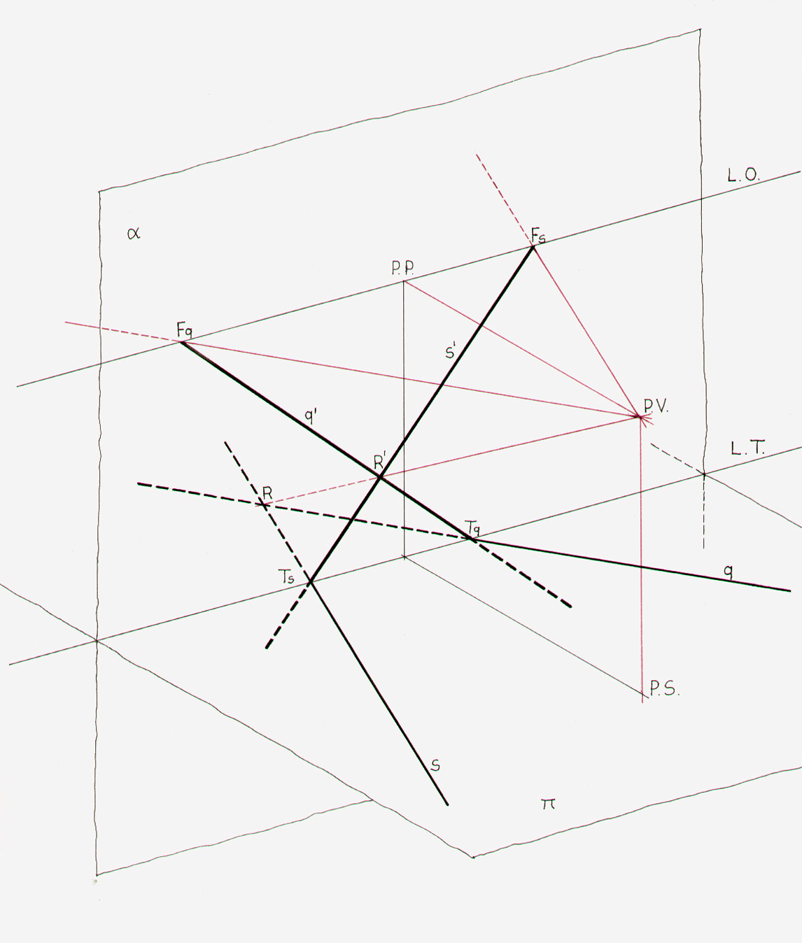
- Central (perspective) projection: projectors meet at a single point (the eye). It produces realistic convergence of parallel lines and is used in art, rendering and architectural perspective (one-, two- and three-point perspective).
- Parallel projection: projectors are parallel. It splits into:
- Orthographic (orthogonal): projectors perpendicular to the projection plane. Used for engineering views (plans, elevations, sections).
- Oblique: projectors at an angle to the plane; includes cavalier and cabinet styles where depth is shown by a receding axis.
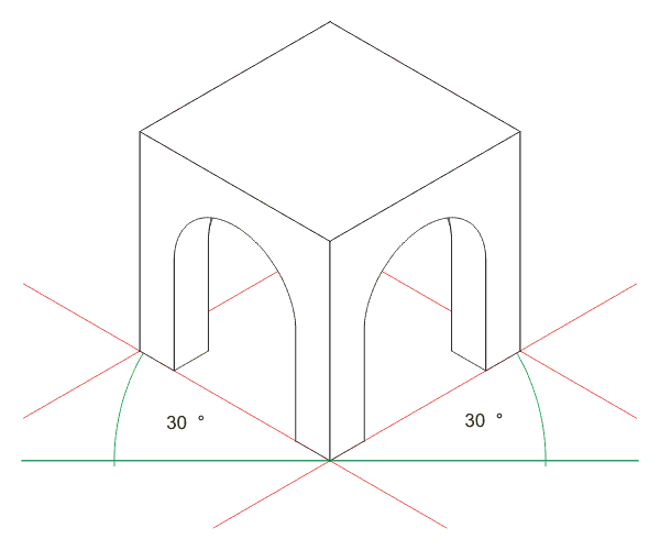
- Axonometric: a form of orthographic parallel projection rotated relative to the object; includes isometric, dimetric and trimetric projections, common for pictorial technical drawings.
Conventions and practical notes
Technical standards govern how projections are presented: for example, first-angle and third-angle projection are conventions that determine view placement on an engineering drawing. Graphical projection also deals with hidden-line representation, scale choices, and foreshortening rules so that dimensions can be measured or interpreted from the drawing.
History and development
The conceptual roots lie in Renaissance perspective, when artists formalized methods to depict depth, and in descriptive geometry of the 18th century, which provided systematic construction rules for projections. During the industrial era projection techniques became standardized for manufacturing and later integrated into computer-aided design (CAD) and 3D graphics, where the same projection principles are implemented algorithmically.
Applications and distinctions
Graphical projection is used to communicate shape and assembly in engineering drawings, to compose realistic scenes in art and visualization, and to design maps and diagrams. It should be distinguished from mathematical projection in pure geometry or map projection on the sphere: the term here emphasizes drawing conventions and readable representation rather than only analytic formulae.
Related articles
Author
AlegsaOnline.com Graphical projection Leandro Alegsa
URL: https://en.alegsaonline.com/art/40349