
Impedance matching in electronics and optics
Impedance matching is the practice of making two systems interact with minimal signal reflection or loss. It applies to electrical circuits, RF systems, audio gear, and optical interfaces.
Overview
Impedance matching is the practice of arranging connections between two systems so that their impedances present compatible conditions for signal transfer. In general, a good match reduces reflections and maximizes the transfer of power or information. The concept appears in both electronics and optics, and it is relevant wherever waves or alternating signals cross a boundary.
Image gallery
3 Images

Basic principles
Electrical impedance combines resistance and reactance into a complex quantity; matching aims to present a conjugate or equal impedance depending on the criterion (maximum power transfer versus minimum reflection). In transmission lines and radio-frequency systems, mismatches create standing waves and return loss. In optics, an analogous idea uses refractive indices and index-matching layers to prevent Fresnel reflections.
Common techniques
- Passive networks: L-networks, Pi- and T-networks built from capacitors and inductors.
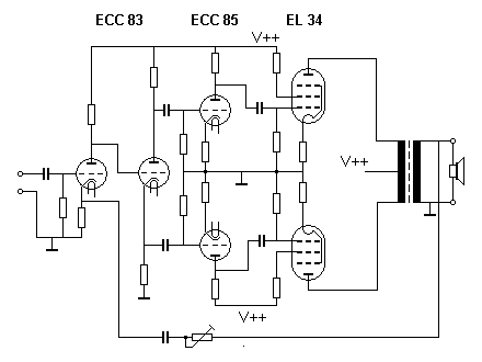
- Transformers and baluns: transform impedances and provide isolation in audio and RF paths.
- Transmission-line methods: quarter-wave transformers and stubs for narrowband matching.
- Optical methods: anti-reflection coatings and immersion fluids to equalize refractive indices.
History and development
The need to match impedances emerged with telecommunications and early radio, as engineers recognized losses from mismatched lines. Tools such as the Smith chart were developed to visualize complex impedances and design matching circuits. Over time the practice extended from telephone and broadcast systems to modern microwave, RF, and photonic devices.
Applications and notable distinctions
Practical applications include antenna feed systems, audio equipment where transformers match microphone or speaker impedances, cable and PCB design to avoid signal integrity issues, and optical coatings for lenses and sensors. Distinctions to note: matching for maximum power transfer is not always identical to minimizing reflections; in some cases, noise figure, bandwidth, or source constraints lead to different optimal solutions. Simple measures such as terminators at characteristic impedance are often sufficient for broadband stability.
Further reading: introductory texts in RF engineering and optics explain matching networks and their trade-offs; simulation tools and measurement instruments like network analyzers assist in practical design.
Related articles
Author
AlegsaOnline.com Impedance matching in electronics and optics Leandro Alegsa
URL: https://en.alegsaonline.com/art/46879