
Stress (mechanics): definition, types, measurement, and engineering use
Mechanical stress is the internal force per unit area within materials. This article explains definitions, stress types, measurement, common formulas, continuum assumptions, and engineering relevance.
Overview
Mechanical stress in solid bodies describes the internal forces distributed over imagined surfaces inside a material that resist externally applied loads. In mechanics, stress quantifies how much force is transmitted through a unit area of the material and how that force tends to change the body's shape or state of motion. It is central to predicting deformation and failure in structures, components and natural materials.
Image gallery
8 Images


Definition and units
At its simplest for a straight uniaxial load, normal stress is given by the ratio σ = F / A, where F is the applied force and A is the cross-sectional area over which the force acts. Units follow from force divided by area: in the International System this is newtons per square metre, which is called the pascal (Pa). Other systems use units such as pounds-force per square inch (psi). Stress has the same dimensional form as pressure, but stress commonly denotes directional internal forces inside solids rather than a scalar isotropic pressure.
Stress as a tensor and common types
In a general three-dimensional body, stress is not a single number but a second-order tensor that relates surface orientation to the traction (vector force per area) across that surface. Components of this tensor include normal stresses (acting perpendicular to a surface) and shear stresses (acting tangentially). The tensorial nature means stress depends on both location and the orientation of the imagined cut through the material.
Principal stresses, invariants and representations
The stress tensor can be diagonalized at a point to find principal stresses: three mutually perpendicular normal stresses that produce no shear on their respective planes. These principal values and other scalar measures (invariants) are widely used in failure criteria and material models. Graphical tools such as Mohr’s circle give a convenient two-dimensional representation of normal and shear stress states for planar problems.
Continuum assumption and common measures
Continuum mechanics treats materials as continuous media so that stress is defined at every point and varies smoothly in space and time for most engineering problems. The most commonly used stress measure in small-deformation analyses is the Cauchy (or true) stress. For large deformations other measures such as the first and second Piola–Kirchhoff stresses are defined to relate forces and areas in different configurations of the body.
Typical applications and examples
Engineers use stress analysis to size structural elements, assess safety factors and predict failure modes. Typical examples include tensile tests that produce mostly normal stress, bending of beams where stress varies linearly through the section, torsion of shafts causing shear stress, and contact problems that create highly localized compressive stresses. Fatigue, yielding and brittle fracture are failure processes intimately tied to the state and history of stress in the material.
Distinctions and practical notes
- Stress vs. strain: Stress is an internal force per unit area; strain measures the resulting relative deformation. Constitutive laws (e.g., Hooke’s law) relate them for many materials.
- Stress vs. pressure: Pressure is an isotropic scalar acting equally in all directions (typical in fluids), whereas stress in solids is generally directional and described by a tensor.
- Local variation: Stress fields are often nonuniform; concentration around holes, notches, sharp corners or contacts can be orders of magnitude higher than nominal values and govern failure.
Historical and theoretical context
The mathematical concept of stress developed during the 19th century as part of the formulation of continuum mechanics. It provided a framework to relate external loads, internal forces and deformation fields in solids and fluids. Modern computational methods, such as the finite element method, numerically solve for stress distributions in complex geometries by discretizing the continuum.
Further reading and resources
- Basic definitions and formulae
- Units and conversions
- Normal and shear stress examples
- Internal forces and particle interactions
- SI units overview
- Force units
- Area units and measures
- Pascal and derived units
- Imperial units context
- Pound-force definition
- Square-inch area unit
- Relation to pressure
- Continuum hypothesis
- Mathematical continuity and fields
- Stress as a function of space and time
- Geometry, energy and stress concentration
Understanding stress and its distribution is fundamental to safe, economical design and to interpreting experimental tests. Modern analysis combines theory, material data and computation to predict how structures will carry loads throughout their intended life.
Interface voltages
→ Main article: Cut reaction
By applying the principle of sectioning, internal stresses of a body can be graphically represented. At an imaginary section at any point of a body, the section forces are applied, which result from the forces acting on the body from the outside and allow the conclusion to be drawn about the internal stresses of the body.
Normal stress, bending stress, shear stress, torsional stress and true stress
For a uniform tensile or compressive load on a bar, the stress is uniformly distributed over the cross-sectional area. The normal stress, i.e. the stress under normal force loading due to tension or compression, is given by

where  is the force in the direction of the surface normal and
  the area of the bar cross-section. For true stresses this is the area in the deformed member and for nominal or engineering stresses it is the nominal value of the undeformed initial member cross section, see tensile test. The stress tensor always has 3 (for all three spatial directions) normal stress components, if this is positive in one spatial direction, tension is present in this spatial direction, likewise with compressive stresses, the normal stress component is then negative in this direction.
When the bar is subjected to a bending load, a bending stress results which is highest at the edge of the bar cross-section (in the so-called edge fibre) and decreases to zero towards the centre (in the so-called neutral fibre). In summary, the bending stress is the compressive and tensile stress caused by the bending in one part of the cross-section at a time:

With constant uniaxial bending 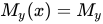 in the principal inertial axis system, the formula simplifies to:

where  is the bending moment about the y-axis,
  is the plane moment of inertia about the y-axis,
  is the distance from the neutral fiber (for σB = 0),
  is the maximum or minimum occurring distance from the axis of gravity to the edge fiber, and is the section
  modulus, see beam theory. The following sketch illustrates this on a cantilever beam:
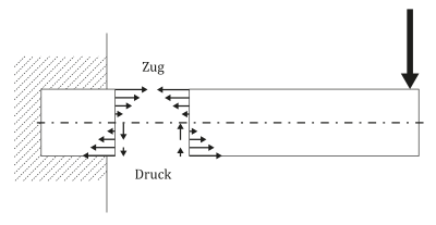
As a vector, the section stress vector has three components that depend on the orientation of the section face. The vertical arrows on the cut edges indicate shear stresses introduced by the shear force. In the case of a profile loaded with a shear force, as shown in the figure, a non-constant shear stress curve occurs across the cross-section. If the shear force acts outside the shear center, torsion also occurs.
In the case of torsion of bars with circular (ring) cross-section, the shear stress is:

Where Mt is the torsional moment, Ip is the polar moment of area inertia, Wt is the torsional moment of resistance, r is the radial cylinder coordinate and ra is the outer radius of the (hollow) cylinder.
The formulas for bending and torsional stress assume linear elasticity.
The tensor calculation allows to describe the stress state at first independent of a certain coordinate system and to adapt it to the geometrical properties of the body only after deriving the respective calculation method (like the formulas above), for example in cylindrical coordinates as in torsion.
Questions and answers
Q: What is stress?
A: Stress is the force per unit area on a body that tends to cause it to change shape. It is a measure of the internal forces in a body between its particles, and is the average force per unit area that a particle of a body exerts on an adjacent particle across an imaginary surface that separates them.
Q: How do external forces affect stress?
A: External forces are either surface forces or body forces, and they cause deformation of the body's shape which can lead to permanent shape change or structural failure if the material is not strong enough.
Q: What is the formula for uniaxial normal stress?
A: The formula for uniaxial normal stress is σ = F/A, where σ is the stress, F is the force and A is the surface area. In SI units, force is measured in newtons and area in square metres, meaning stress would be newtons per square meter (N/m2). However, there exists its own SI unit for stress called pascal (Pa), which equals 1 N/m2. In Imperial units, it would be measured in pound-force per square inch (psi).
Q: What does continuum mechanics assume about force?
A: Classical models of continuum mechanics assume an average force and do not properly include geometrical factors - meaning they don't take into account how geometry affects how energy builds up during application of external force.
Q: How can different models give different results when looking at deformation of matter and solid bodies?
A: Different models look at deformation of matter and solid bodies differently because characteristics of matter and solids are three dimensional - so each approach takes into account different aspects which can lead to varying results.
Q: How does continuum mechanics treat loaded deformable bodies?
A: Continuum mechanics treats loaded deformable bodies as continua - meaning internal forces are distributed continually within volume of material body instead being concentrated at certain points like with classical models.
Related articles
Author
AlegsaOnline.com Stress (mechanics): definition, types, measurement, and engineering use Leandro Alegsa
URL: https://en.alegsaonline.com/art/94272
Sources
- books.google.com : Computational elasticity: theory of elasticity and finite and boundary element methods
- books.google.com : Theory of elasticity for scientists and engineers
- books.google.com : Continuum mechanics: concise theory and problems
- books.google.com : Theory of plasticity
- books.google.com : Mathematical Theory of Continuum Mechanics
- books.google.com : Plasticity for structural engineers
- books.google.com : Classical and computational solid mechanics
- books.google.com : Fundamentals of Machine Elements
- books.google.com : Fundamentals of structural mechanics
- books.google.com : Continuum mechanics
- books.google.com : Fundamentals of rock mechanics
- ce.berkeley.edu : Plasticity Theory (Revised Edition)
- books.google.com : Continuum Mechanics
- books.google.com : Continuum Mechanics for Engineers
- books.google.com : Introduction to mechanics of continua