
Power factor: definition, causes, correction and practical significance
Power factor is the fraction of apparent electrical power that does real work. This article explains its meaning, calculation, common causes of low PF, correction methods and practical implications.
Overview
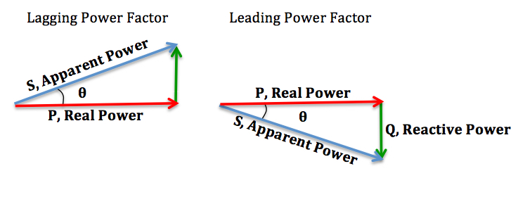
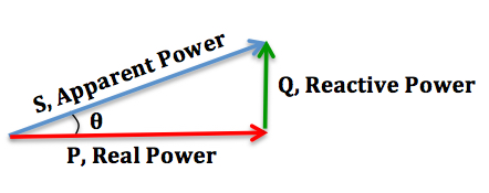
Power factor (PF), often written as cos φ, quantifies how effectively an AC electrical system converts the product of voltage and current into useful work. In simple terms it is the ratio of real power (the energy per unit time actually consumed to perform work) to apparent power (the product of RMS voltage and RMS current). A higher power factor means a greater portion of the supplied current contributes to useful power, while a low power factor indicates more current is circulating without producing work.
Image gallery
8 Images



How power factor is calculated
For sinusoidal, linear circuits the relationship is commonly expressed as P = V·I·cos φ, where P is real power and V·I is apparent power S. The power factor is therefore PF = P / S and its magnitude ranges from 0 to 1 for purely sinusoidal cases; the phase angle φ indicates whether the current leads or lags the voltage (commonly described as leading or lagging). In modern systems with waveform distortion the overall PF may be reduced further by harmonic currents; engineers distinguish displacement power factor (due to phase shift) from distortion power factor (due to waveform shape).
Common causes of low power factor
- Inductive loads such as motors, transformers and reactors, which cause current to lag voltage.
- Capacitive loads in some specialized equipment, which can lead current to lead voltage.
- Nonlinear loads (rectifiers, variable-frequency drives, switching supplies) that introduce harmonics and reduce the effective PF.
- Underloaded machines and long distribution networks that increase reactive currents relative to real power.
Methods for improving power factor
Organizations reduce reactive current and restore PF using several well-established methods. Passive capacitor banks provide local reactive power compensation and are common in industrial installations. Synchronous condensers (synchronous motors operated without mechanical load) can produce or absorb reactive power under control. Active power factor correction circuitry inside electronic equipment improves PF at the point of use. In larger systems utilities and engineers may combine these approaches and add filters to limit harmonic distortion.
Practical importance and examples
Improving PF reduces current drawn for a given real load, which lowers I2R losses in conductors, frees capacity in transformers and feeders, and can avoid utility penalties for poor PF. For example, an industrial site with many induction motors typically installs capacitor banks near motor feeders; data centers employ active PFC in power supplies to meet standards. Measuring and correcting PF is part of good electrical design and energy management.
Measurement, standards and notable distinctions
Power factor is measured with power meters, analyzers or specialized PF meters that report real, reactive and apparent power plus harmonic content. Standards and incentive structures vary by jurisdiction: some utilities bill customers for low PF or require corrective equipment. When assessing PF, it is important to separate displacement (phase shift) issues from distortion (harmonics) because remedies differ: capacitors address displacement but can worsen harmonic problems unless filters are used. For additional technical background see electric power references, explanations of the ratio concept, discussions of voltage-current relationships and practical material on circuit behavior.

Impact factor
Exclusively for sinusoidal currents and voltages, the effective factor is defined from the ratio  . It is equal to the cosine of the phase shift angle φ
  , see the graph opposite.
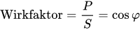
The amount of the effect factor is defined as the displacement factor.
Non-sinusoidal quantities contain, in addition to the fundamental, harmonics for which no uniform phase shift angle can be specified. In this case, the power factor λ  cannot be specified as the effective factor
  . Harmonics are to be expected in particular in power supplies with conventional bridge rectifier, switching power supplies and loads containing semiconducting or magnetic components with non-linear characteristics.
In order to designate the characteristics of the load, the correct designation of the reactive power flow direction must be ensured. Clear designations are "inductive acting" and "capacitive acting" (  or
or  in the load metering arrow system).

Meaning
In power supply installations, the aim is to achieve the highest possible power factor in order to avoid transmission losses. Ideally, it is exactly 1, but practically it is only about 0.95 (inductive). In motor systems with asynchronous machines, there is a risk of self-excitation if the reactive power is fully compensated. In addition, a capacitive power factor would lead to overvoltages on insulation of lines and electrical consumers. Power supply companies often prescribe a power factor of at least 0.9 for their customers. If the power factor falls below this value, the reactive energy purchased is billed separately. For private households, however, this is irrelevant. Power factor correction systems are used to increase the power factor. Since 1 January 2012, photovoltaic systems in Germany must also be capable of under-excited to overexcited between 0.9 or 0.95, depending on the size of the system, in order to stabilise the local grid voltage according to the requirements of the grid operator.
Related articles
Author
AlegsaOnline.com Power factor: definition, causes, correction and practical significance Leandro Alegsa
URL: https://en.alegsaonline.com/art/78523