Polar coordinate system
![]()
This article deals with polar coordinates of the plane as well as the closely related cylindrical coordinates in space. For spatial polar coordinates see the article Spherical coordinates.
In mathematics and geodesy, a polar coordinate system (also: circular coordinate system) is a two-dimensional coordinate system in which each point in a plane is defined by the distance from a given fixed point and the angle to a fixed direction.
The fixed point is called the pole; it corresponds to the origin in a Cartesian coordinate system. The ray emanating from the pole in the specified direction is called the polar axis. The distance from the pole is usually denoted by 


Polar coordinates are a special case of orthogonal curvilinear coordinates. They are useful when the relationship between two points can be described more easily by angles and distances than would be the case with 

In mathematics, the angular coordinate is measured in the mathematically positive direction of rotation (counterclockwise). If a Cartesian coordinate system is used at the same time, its coordinate origin usually serves as the pole and the 


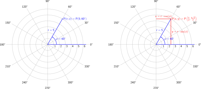
A polar grid of different angles with degrees
History
The terms angle and radius were already used by the ancients in the first millennium BC. The Greek astronomer Hipparchus (190-120 BC) created a table of trigonometric chord functions to find the length of the chord for each angle. With this basis he was able to use polar coordinates to determine the position of certain stars. However, his work covered only a part of the coordinate system.
In his treatise On Spirals, Archimedes describes a spiral line with a function whose radius changes depending on its angle. However, the Greek's work did not yet include a full coordinate system.
There are different descriptions to define the polar coordinate system as part of a formal coordinate system. The whole history on this subject is summarized and explained in the book Origin of Polar Coordinates by the Harvard professor Julian Coolidge. According to it Grégoire de Saint-Vincent and Bonaventura Cavalieri introduced this conception independently of each other in the middle of the 17th century. Saint-Vincent wrote on the subject privately in 1625 and published his work in 1647, while Cavalieri published his elaboration in 1635, with a corrected version appearing in 1653. Cavalieri initially used polar coordinates to solve a problem concerning the area of the Archimedean spiral. Somewhat later, Blaise Pascal used polar coordinates to calculate the length of parabolic angles.
In the work Method of Fluxions (written 1671, published 1736), Sir Isaac Newton considers the transformation between polar coordinates, to which he referred as "Seventh Manner; For Spirals," and nine other coordinate systems.
He was followed by Jacob Bernoulli, who used a system consisting of a straight line and a point on this straight line, which he called polar axis or pole, in the technical journal Acta Eruditorum (1691). In it, the coordinates were defined by the distance from the pole and the angle to the polar axis. Bernoulli's work extended to the formulation of the circle of curvature of curves, which he expressed by the mentioned coordinates.
The term polar coordinates in use today was finally introduced by Gregorio Fontana and used in 18th century Italian writings. Subsequently, George Peacock adopted this term into the English language in 1816 when he translated the work of Sylvestre Lacroix Differential and Integral Calculus into his language.
Alexis-Claude Clairaut, on the other hand, was the first to think about polar coordinates in three dimensions, but it was the Swiss mathematician Leonhard Euler who succeeded in developing them.
Polar coordinates in the plane: circular coordinates
Definition
The polar coordinates of a point in the Euclidean plane (plane polar coordinates) are specified with respect to a coordinate origin (a point in the plane) and a direction (a ray starting at the coordinate origin).
The polar coordinate system is unambiguously defined by the fact that an excellent point, also called pole, forms the origin/zero point of the coordinate system. Furthermore, a ray emanating from it is distinguished as the so-called polar axis. Finally a direction (of two possible), which is perpendicular to this polar axis, must be defined as positive, in order to determine the sense of rotation / the direction of rotation / the orientation. Now an angle, the polar angle, can be defined between any ray passing through the pole and this distinguished polar axis. It is unique only up to integer revolutions around the pole, independently of what is chosen as angle measure for it. On the pole axis itself there is still an arbitrary but fixed scaling to define the radial unit length. Now each pair 
Plane polar coordinates (with angles in degrees) and their transformation into Cartesian coordinates
The coordinate 

In mathematics, the counterclockwise angle is usually defined as positive when looking vertically at the plane (clock) from above. So the direction of rotation goes from right to top (and further to the left). As angle measure the radian is preferred as angle unit, because it is then analytically most elegant to handle. The polar axis typically points to the right in graphical representations of the coordinate system.
Conversion between polar coordinates and Cartesian coordinates
Conversion from polar coordinates to Cartesian coordinates
If one chooses a Cartesian coordinate system with the same origin as the polar coordinate system, thereby the 


Conversion from Cartesian coordinates to polar coordinates
The conversion of Cartesian coordinates into polar coordinates is somewhat more difficult, because mathematically one always depends on a trigonometric inverse function (which does not cover the entire range of values of the solid angle). First, however, the radius 
When determining the angle φ two peculiarities of polar coordinates must be taken into account
- For
the angle φ is
not uniquely determined, but could take any real value. For a unique transformation rule, it is often defined to be 0. The following formulas are
given under the condition to simplify their derivation and presentation.
- For
the angle φ is
determined
only to integer multiples of since the angles φ {\displaystyle
and φ
(for
) describe the same point. For the purpose of a simple and unambiguous transformation rule, the angle φ
is
restricted to a half-open interval of length Usually, depending on the application, the intervals
or
chosen.
For the calculation of φ 
can be used. However, this does not uniquely determine the angle, even in the interval ![(-\pi ,\pi ]](https://www.alegsaonline.com/image/7fbb1843079a9df3d3bbcce3249bb2599790de9c.svg)


Calculation of the angle in the interval [-π, π] or [-180°,180°].
Using the arc tangent, φ can be calculated 
![(-\pi ,\pi ]](https://www.alegsaonline.com/image/7fbb1843079a9df3d3bbcce3249bb2599790de9c.svg)
![{\displaystyle (-180^{\circ },180^{\circ }]}](https://www.alegsaonline.com/image/52564e11cb8ecd24997d7929ef3ff9a87052b335.svg)
Some programming languages (such as Fortran 77) and application programs (such as Microsoft Excel) provide an 


The same result is obtained if the point 


With the help of the arc cosine one gets along with only two case distinctions:
By taking advantage of the fact that in a circle a central angle is always twice as large as the corresponding circumferential angle, the argument φ can 
Calculation of the angle in the interval [0, 2π) or [0, 360°)
The calculation of the angle φ


![(-\pi ,\pi ]](https://www.alegsaonline.com/image/7fbb1843079a9df3d3bbcce3249bb2599790de9c.svg)

By modifying the first formula above, φ
The formula with the arc cosine gets along with only two case distinctions also in this case:
Shifting the angle
In geodetic or other calculations, azimuths φ may differ 


shifts φ 


Functional determinant
From the conversion formulas from polar coordinates to Cartesian coordinates one obtains for the functional determinant as determinant of the Jacobi matrix:
Area element
With the functional determinant, the result for the area element in polar coordinates is:
As the accompanying figure shows, the area element can be interpreted as a differential rectangle with width 

Line element
From the above transformation equations
follow
The following applies to the Cartesian line element
for which in polar coordinates follows:
Velocity and acceleration in polar coordinates
For this purpose, the motion is decomposed into a radial and a perpendicular "transversal" component. For the velocity vector 
with unit vectors 

For the acceleration 

Spatial polar coordinates: Cylinder coordinates and spherical coordinates
Cylinder coordinates
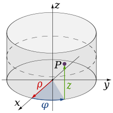
Cylinder coordinates or cylindrical coordinates are essentially plane polar coordinates with a third coordinate added. This third coordinate describes the height of a point vertically above (or below) the plane of the polar coordinate system and is generally 


Conversion between cylindrical coordinates and Cartesian coordinates
If you align a Cartesian coordinate system so that the 


For the conversion of Cartesian coordinates into cylindrical coordinates the same formulas result for ρ 

Basis vectors
The basis vectors 


Functional determinant
The addition of the rectilinear coordinates 
Consequently, for the volume element 
This also corresponds to the square root of the amount of the determinant of the metric tensor, with the help of which the coordinate transformation can be calculated (see Laplace-Beltrami operator).
Vector Analysis
The following representations of the Nabla operator can be applied in the given form directly to scalar or vector-valued fields in cylindrical coordinates. The procedure is analogous to the vector analysis in Cartesian coordinates.
Gradient
The representation of the gradient transfers from Cartesian to cylindrical coordinates as follows:
Divergence
In the case of divergence, additional terms are added, resulting from the derivatives of the unit vectors depending on ρ 


Rotation
The representation of the rotation is as follows:
Spherical coordinates
→ Main article: Spherical coordinates
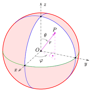
Spherical coordinates are essentially plane polar coordinates with a third coordinate added. This is done by specifying an angle θ![\theta \in [0,\pi ]](https://www.alegsaonline.com/image/c833964ea08aa30df8b6f56664461a5499b38144.svg)


Cylinder coordinates

Spherical coordinates
n-dimensional polar coordinates
It is also possible to give a generalization of polar coordinates with 


![\vartheta_{n-2}\in [0,\pi]](https://www.alegsaonline.com/image/fd757b4fc3635a37579afba4382be3d4cda87789.svg)


![{\displaystyle \varphi =\vartheta _{0}\in [0,\pi ]}](https://www.alegsaonline.com/image/049d26ceee7c1903d4aefcec69374863275f25f7.svg)

Conversion to Cartesian coordinates
A conversion rule from these coordinates to Cartesian coordinates would then be:
As can be shown, these polar coordinates change into the ordinary polar coordinates for the case 
Functional determinant
The functional determinant of the transformation from spherical coordinates to Cartesian coordinates is:
Thus, the 
Note: 


Search within the encyclopedia


