Oscilloscope — Instrument for Displaying Electrical Signals
A technical overview of oscilloscopes: what they are, main parts and controls, types and history, common applications, and distinctions from related test instruments.
Overview
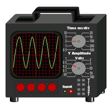
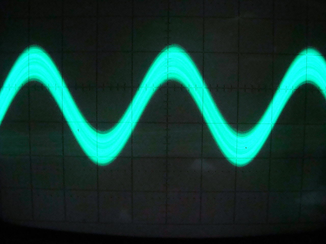
An oscilloscope is an electronic instrument that graphically displays how electrical signals change over time. By plotting voltage on a vertical axis against time or another voltage on a horizontal axis, it reveals waveform shape, amplitude, frequency, phase relationships and transient events. The classic vacuum-tube device is often called a cathode ray oscilloscope (cathode ray or CRO), while contemporary instruments are more commonly digital.
Image gallery
10 Images


Characteristics and main parts
Most oscilloscopes share a set of basic elements and controls that make them useful for signal analysis. Key components include probes or inputs, an input amplifier, timebase and trigger circuitry, a display system, and user controls to adjust scale and position. Important performance characteristics engineers consider are bandwidth, sampling rate, input impedance, and memory depth; these determine the range of signals the instrument can capture accurately.
- Inputs and probes: passive and active probes, differential probes, and BNC connectors.
- Vertical controls: voltage scale and coupling (AC/DC).
- Horizontal/timebase: sweep speed and position.
- Triggering: level, edge, and more advanced modes to stabilize repetitive or single-shot waveforms.
History and evolution
Early oscilloscopes used cathode ray tubes to paint a trace on a phosphor screen. Over decades the instrument evolved from single-trace analog scopes to dual- and multiple-trace models, and eventually to digital storage oscilloscopes (DSOs) that sample signals and display them using digital memory. Later innovations added mixed-signal capabilities, deeper memory, higher sampling rates and software-based analysis, making oscilloscopes versatile tools for modern electronics.
Common uses and examples
Oscilloscopes are indispensable in electronics design, repair and education. Typical tasks include checking clock signals, measuring pulse width and rise/fall times, diagnosing analog circuit behavior, and observing noise or interference. They are used in laboratories, manufacturing test benches, automotive diagnostics, telecommunications and research. When combined with spectrum or protocol decoding options, they provide both time-domain and protocol-level insight.
Distinctions and practical tips
Oscilloscopes differ from multimeters and logic analyzers: a multimeter gives steady-state values like voltage or resistance, while a logic analyzer records many digital lines but usually lacks analog detail. Choosing an oscilloscope involves balancing bandwidth and sampling rate for the signals of interest, selecting appropriate probes, and using triggering to capture elusive events. For accurate measurement, probe compensation and proper grounding are essential practices.
Questions and answers
Q: What is an oscilloscope?
A: An oscilloscope is a piece of electronic equipment that allows you to view changes in signal voltage.
Q: What does the abbreviation CRO stand for?
A: CRO stands for cathode ray oscilloscope.
Q: How can an oscilloscope be used to view the signal produced by an electronic timer?
A: To view the signal produced by an electronic timer, the timer can be connected to an oscilloscope.
Q: What does an oscilloscope typically display?
A: An oscilloscope typically displays a two-dimensional graph of one or more electrical potential differences.
Q: What is usually plotted along the horizontal axis of an oscilloscope graph?
A: The horizontal axis of an oscilloscope graph typically shows time or some other voltage.
Q: What is the purpose of an oscilloscope?
A: The purpose of an oscilloscope is to visualize changes in signal voltage.
Q: Can an oscilloscope measure sound waves?
A: Yes, an oscilloscope can measure sound waves as they are also changes in signal voltage.
Related articles
Author
AlegsaOnline.com Oscilloscope — Instrument for Displaying Electrical Signals Leandro Alegsa
URL: https://en.alegsaonline.com/art/73361