
Logic gate
A logic gate is a basic digital component that performs Boolean operations on binary inputs. This article explains types, implementation, history, common uses, and important properties such as universality and timing.
A logic gate is a fundamental building block of modern electronics that produces an output signal according to a simple rule applied to one or more input signals. In digital systems inputs and outputs represent two discrete states, commonly called 1 and 0, true and false, or On and Off. The behaviour of a gate is described by Boolean expressions and by a truth table that lists the output for every possible combination of inputs.
Image gallery
4 Images

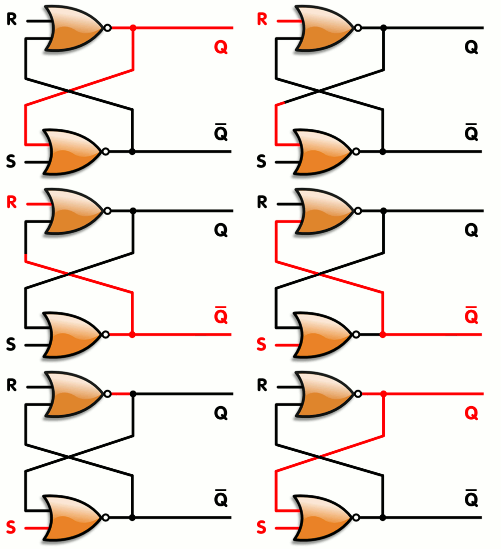

Common types and their behaviour
Basic gates implement the elementary Boolean operations:
- AND: output is 1 only if every input is 1.
- OR: output is 1 if any input is 1.
- NOT (inverter): output is the logical complement of the input.
- NAND and NOR: the complements of AND and OR; each is functionally complete (universal).
- XOR (exclusive OR): output is 1 when an odd number of inputs are 1.
- XNOR: the complement of XOR; output is 1 when inputs are equal.
Small truth tables can be written inline, for example AND with two inputs A and B: A=0, B=0 -> 0; A=0, B=1 -> 0; A=1, B=0 -> 0; A=1, B=1 -> 1. These basic gates are combined to form larger combinational and sequential circuits.
Physical implementation and electrical characteristics
Logic gates are implemented using semiconductor devices such as transistors, and packaged as individual chips or as part of larger integrated circuits. They operate using discrete voltage levels to represent logic states; common supply voltages include 5 V and 3.3 V but many families use lower voltages. Gates respond to the presence or absence of an input voltage and produce an output current; the underlying behavior depends on transistor technologies like TTL or CMOS.
Important practical parameters include propagation delay (how long a gate takes to change its output), fan-in (number of inputs a gate can accept), fan-out (how many inputs a gate output can drive), power consumption drawn from power rails, and noise margins that determine reliability in the presence of signal variations.
History and development
Logical switching predates modern transistors: relay-based and vacuum-tube circuits implemented Boolean functions in early computers. The invention of the transistor in the mid-20th century led to smaller, faster gates. The rise of integrated circuits allowed thousands to millions of gates on a single chip, enabling the complex processors and memory arrays found in contemporary devices. Designers now use schematic tools and hardware description languages to specify gate-level behavior for synthesis into silicon.
Uses, examples, and design patterns
Gates are composed to create arithmetic units, multiplexers, encoders, decoders, flip-flops and memory cells. For example, a half-adder uses an XOR gate and an AND gate to produce sum and carry outputs. In larger systems, gates are organized into combinational blocks (output depends only on current inputs) and sequential blocks (output depends on current inputs and stored state). They form the core of digital logic used in processors, controllers, communication hardware, and signal processing.
Notable properties and practical considerations
Two notable facts: NAND and NOR gates are universal, meaning any Boolean function can be implemented using only one of those types; and real gates are not ideal — transitions take time and can produce transient hazards in asynchronous designs. Engineers use Boolean algebra and logic minimization techniques to reduce gate count, and they add buffering, synchronization, and timing analysis to ensure reliable behaviour in complex electronic circuits.
Finally, while the dominant form is binary logic, research and specialized applications sometimes use multi-valued logic or analog processing where continuous signals carry information. For most practical digital systems, however, binary logic gates remain the essential primitives that implement computation and control.
For further technical reference see an overview of the component role in systems (electronic component), the physics of currents and signals (electric current), and foundational material on logic and circuit families (voltage level, power rails, Boolean logic).
Questions and answers
Q: What is a logic gate?
A: A logic gate is an electronic component that can be used to conduct electricity based on a rule. The output of the gate is determined by applying this rule to one or more inputs, which may be two wires or the output of other logic gates.
Q: How do logic gates work?
A: Logic gates normally work at only two levels of voltage, a positive level and zero level. Commonly they work based on two states - On and Off. In the On state, voltage is positive and in the Off state, voltage is at zero. The On state usually uses a voltage in the range of 3.5 to 5 volts but this range can be lower for some uses. Logic gates compare the state at their inputs to decide what the state at their output should be and are active when their rules are correctly met.
Q: What type of logic do logic gates use?
A: Logic gates are electronic versions of Boolean logic, which means that truth tables will tell you what the output will be depending on the inputs given.
Q: Are all voltages for an "On" state equal?
A: No, not all voltages for an "On" state are equal as it usually uses a voltage in the range of 3.5 to 5 volts but this range can be lower for some uses.
Q: Do all types of logic gates have two inputs?
A: Not necessarily - some types may have more than two inputs while others may have only one input or none at all depending on its purpose and design.
Q: Is there always electricity flowing through a logic gate when it's active?
A: Yes, when a logic gate is active or its rules are correctly met then electricity will flow through it and its output will be set to its On State Voltage level (usually between 3-5V).
Related articles
Author
AlegsaOnline.com Logic gate Leandro Alegsa
URL: https://en.alegsaonline.com/art/58861