Lock (water transport)
A lock is a gated chamber on a canal or river that raises or lowers boats between stretches of water at different levels, enabling navigation past falls, dams, weirs, or steep gradients.
Overview
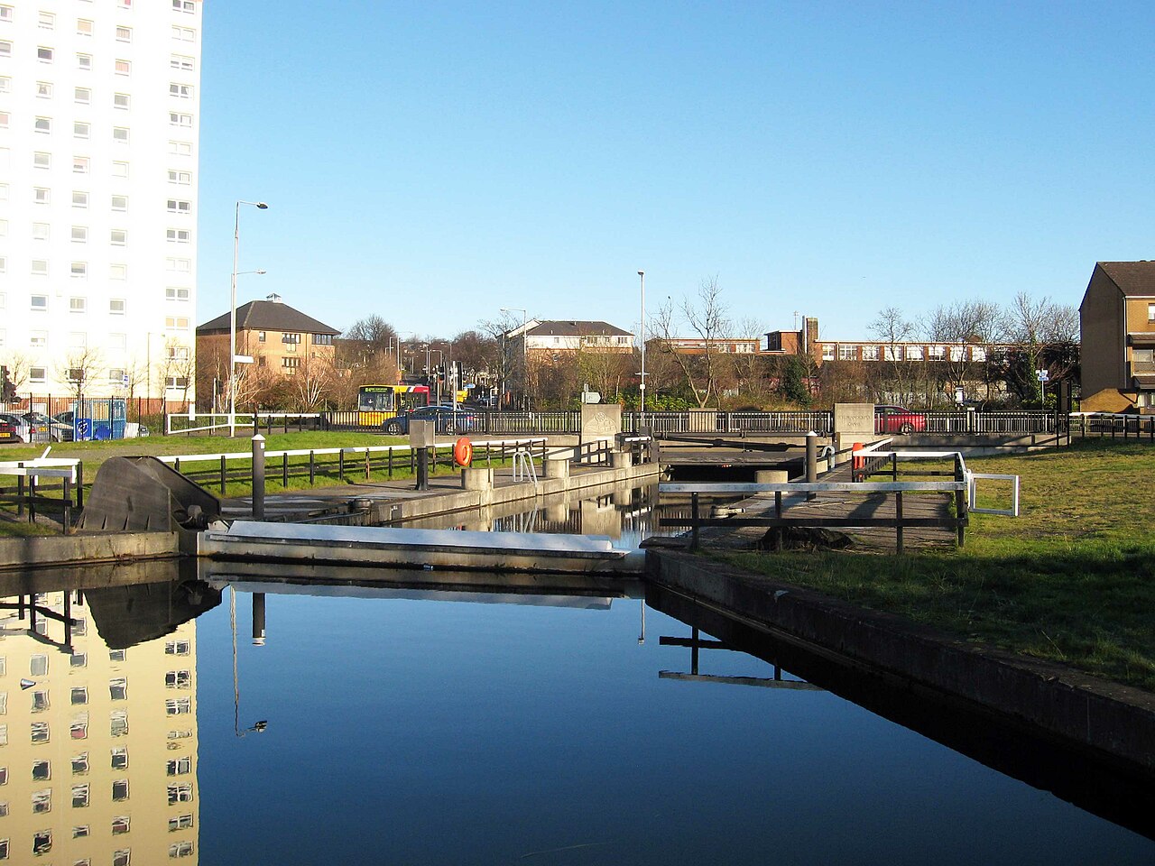
A lock is a mechanized chamber in a navigable waterway that allows vessels to move between reaches of different surface elevations. Locks are installed where natural or artificial obstacles produce abrupt level changes in a river or canal: for example a waterfall, a dam or a weir. By isolating a section of channel and controlling the inflow and outflow of water, a lock raises or lowers boats so that inland navigation remains continuous and reliable, improving overall navigability.
Image gallery
10 Images


Components and how a lock works
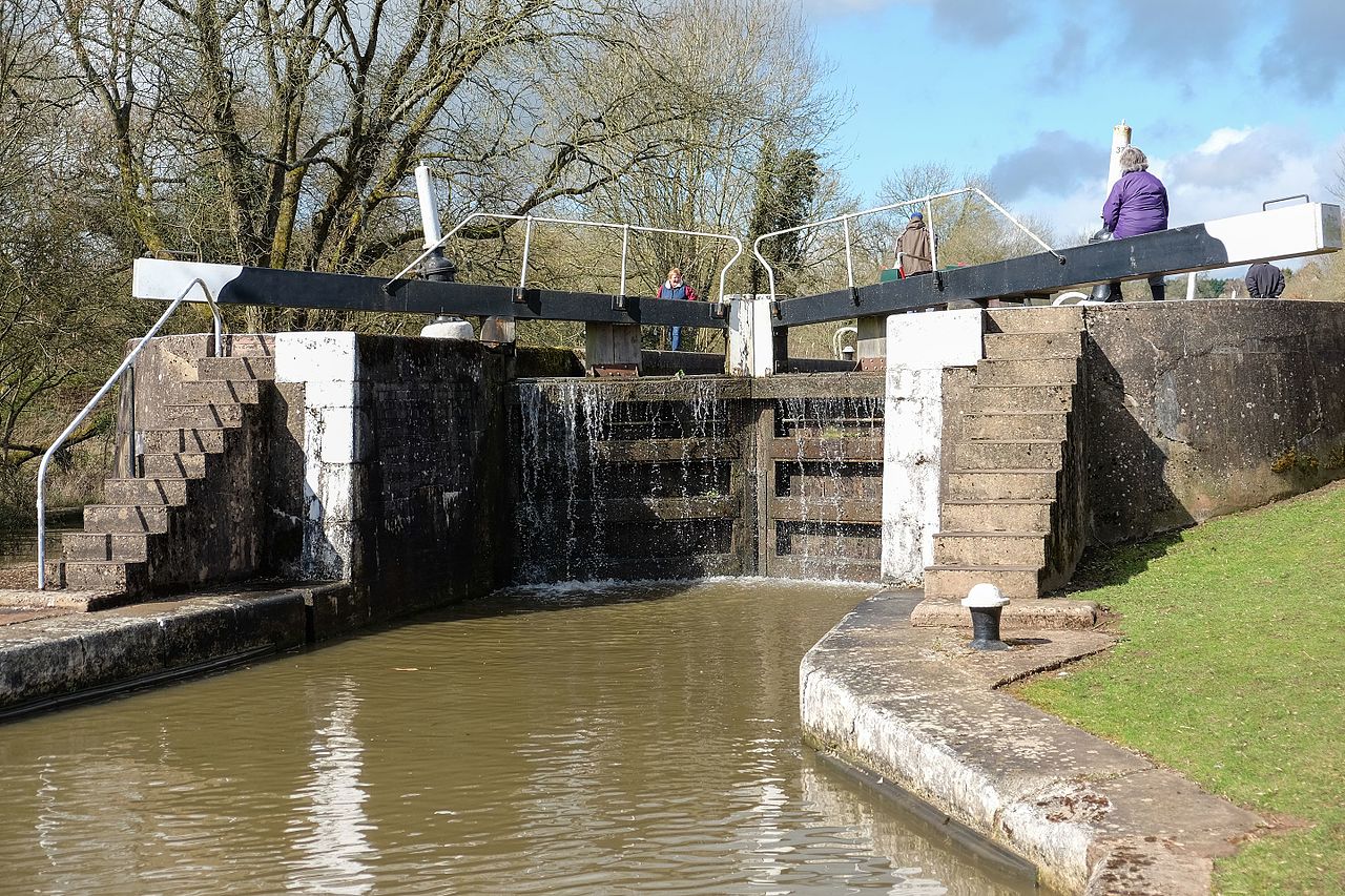
A typical lock consists of a watertight chamber with gates at each end and sluices, valves or culverts to admit and discharge water. Common components include:
- Chamber: the enclosed space that holds the vessel while its level is adjusted.
- Gates: usually two sets, one at the upper end and one at the lower; designs vary from mitre gates to vertical lift or sector gates.
- Filling and emptying gear: paddles, valves or culverts used to change the chamber water level.
- Control mechanisms: manual or powered devices that operate gates and valves, and provide safety features.
Basic operation follows a sequence: the boat enters the chamber; gates close; valves are opened to equalize the chamber with the higher or lower level depending on travel direction; once levels match, the opposite gates open and the craft exits. Locks range from small single chambers for pleasure craft to large multi-gate systems built for ocean-going ships.
History and development
Locks have been developed incrementally over centuries. Early forms appeared in China and Europe to manage irrigation and navigation. The introduction of the mitre gate in the 18th century and later mechanized valves allowed larger and more efficient locks, which were integral to the expansion of inland trade during the Industrial Revolution. Modern locks incorporate electric or hydraulic actuators, remote monitoring and traffic-control systems to improve safety and throughput.
Uses, examples and importance
Locks enable continuous inland waterways across uneven terrain, permitting the movement of cargo, passengers and recreational vessels. Notable examples include flight locks—series of closely spaced chambers—used on steep stretches, and ship locks on major waterways that permit ocean vessels to access inland ports. Locks are also crucial for water-level management in urban areas, for flood control, and as part of reservoir and dam operations.
Variations and notable facts
Types of locks include pound locks (the common chamber type), chamberless tidal locks for estuaries, vertical-lift and boat lifts that use mechanical hoists, and staircase locks where chambers are directly adjacent. While locks conserve water by reusing chamber volumes, large installations may employ side ponds or pumps to reduce water loss. Operating a lock requires attention to vessel size, clearance, and safety rules; many historic locks remain in operation and are heritage features of canal networks.
Further reading
For technical details and local operational rules, consult navigation authorities and canal guides. See resources on navigable waterway design, river engineering and lock maintenance practices for deeper information.


General
The word sluice is derived from the Middle Latin sclusa ("weir"), which has its origin in the Latin excludere ("to exclude"). The term stands for the closure of an opening within a transverse structure that dams a body of water. For this reason, the first locks were called barrage locks. In a broader sense, a sluice limits the "flowing" in its discharge by time and quantity. (p. 1) In French it became écluse, and in Spain esclusa is common. Dutch calls these technical devices sluizen as the plural of sluis, and in English the sluices are called locks (English lock).
In addition to ship lifts, inclined planes and boat lanes (for smaller pleasure craft), locks are among the descent structures in transport hydraulic engineering. Generally, locks are used for drop heights of up to about 25 metres, and ship lifts are usually built for greater heights. The first exception in Germany will be the new Lüneburg lock, which will have a lifting height of 38 metres.
In general, locks can be divided into sea locks and inland locks. Due to the size of seagoing vessels, sea locks are significantly larger than inland locks, which are divided into river locks and canal locks. Port locks are often part of a port or are located at its entrance, regardless of whether it is a sea or inland port. Sometimes port locks are called such only because they are located near a port.
The different designs or types of chamber sluices are further developments and adaptations to take account of the different operational, topographical and water management requirements. The special forms are, for example, those for large lifting heights, busy waterways or areas with little water.
In addition to their function for navigation as a connecting element of waterways, locks are also used within the framework of water management as barrage locks to regulate water levels and flow.
For details see section: Locking gates
Terms
Locks are located at barrages, canal stages, waterway crossings, barrage facilities or port facilities. If two or more locks are constructed independently of each other, they are referred to as a group of locks. Otherwise, the terms lock system or lock complex are commonly used for several locks.
The process of passing through a lock is a lockage. Depending on the direction, a distinction is made between upstream lock (upstream lock) and downstream lock (downstream lock). The area in front of the lock with the higher water level is called headwater (also upper current) and the other is called tailwater (also lower current). In these two areas are the outer harbours, where the ships can moor to wait for the lock.
See also: Lock outer harbour
The ships enter the lock chamber from the outer harbours. It is bounded on both sides by the head and the tail, in which the lock gates are located. The draught at the lock heads determines the maximum possible draught of the ships for the lock passage. The position of the jetties may be marked by yellow lines on the chamber wall, which determines the useful length of the chamber. During lockage, the closing devices remain closed so that the chamber water level can be changed independently of the external water levels.
The filling of the lock chamber is usually done by taking water from the headwater and emptying it by letting it down into the tailwater. In the simplest case, this is done via closable openings in the gate or by opening it gently and carefully. In any case, filling and emptying should always be done gently so as not to create strong ship movements inside and outside the chamber. In most cases, lockable circulation channels are arranged on both sides of the lock heads for this purpose, the construction of which is relatively complex. It is very helpful to have a sufficiently dimensioned bottom run under the chamber bottom, from which the filling and emptying takes place very evenly.
See also: Lock chamber
The lock gates must seal off the lock chamber as tightly as possible from the adjoining canal stops. For safety reasons, they must extend approx. one metre above the water level in the headwater or tailwater. Depending on the application, different types of sluice gates are used. The most important are: Mortise gate, lift gate, flap gate, segment gate and sliding gate. (p. 54) A fully functional sluice gate is a prerequisite for controlled sluice operation. Therefore, the gates must be specially protected against damage. The greatest danger arises when a ship enters the lock if it can no longer be stopped in front of the gate. Special impact protection equipment with damping elements can prevent or at least mitigate this. For ram gates, there are gate niches in the sides of the lock heads into which the gate swings when it opens, so that the ships have completely free passage. The same applies to flap gates and segment gates, which are placed in a recess in the floor.
See also: Lock gate

Questions and answers
Q: What is a lock in a navigable waterway system?
A: A lock is a part of a navigable waterway system that makes a water channel deep enough for vessels to use.
Q: What is the purpose of a lock in a waterway system?
A: The purpose of a lock is to control pool depths, and move boats that travel up or down a river or canal to the next higher or lower level.
Q: Why are locks built in waterways?
A: Locks are built in waterways where the level of the water suddenly changes because of a waterfall, dam, weir, or some other obstruction.
Q: What is the structure of a lock?
A: A lock is like a big chamber with gates at each end, and lock gears which empty or fill the chamber with water.
Q: How do locks make it easier for boats to travel up and down a river?
A: Locks help a river to be more easily navigable since they control the water levels of the river, making it deeper in certain areas, and allowing boats to move up and down through the locks.
Q: What is the benefit of building locks across country that is not level?
A: Locks can be built in areas of varying terrain to make it easier for canals to be built across country that is not level.
Q: What does a lock and dam system do?
A: A lock and dam system is used to control water flow and pool depths in a waterway, and to move boats up or down through locks.
Related articles
Author
AlegsaOnline.com Lock (water transport) Leandro Alegsa
URL: https://en.alegsaonline.com/art/58766