LC circuit
An electric resonant circuit, also known as a resonant circuit, is a resonant electrical circuit consisting of a coil (component L) and a capacitor (component C) that can perform electrical oscillations. The electric resonant circuit is often compared to the harmonic oscillator of mechanics such as the spring pendulum or tuning fork. In this LC resonant circuit, energy is periodically exchanged between the magnetic field of the coil and the electric field of the capacitor, resulting in alternating high current or high voltage. The resonant frequency is calculated to:
where 

If a resonant circuit is triggered once by a switching operation or a pulse, then it performs free oscillations (natural oscillations), which in reality decay after a certain time due to losses. However, if it is periodically excited in the range of its resonant frequency, then it performs forced oscillations. The resonance phenomena that occur in this process are of paramount importance for practical applications.
In the case of a resonant circuit with external excitation, a distinction is made between a parallel resonant circuit (L parallel to C) and a series resonant circuit (L in series with C), depending on the arrangement in relation to the excitation source. Inaccurately, the series resonant circuit is sometimes also referred to as a series resonant circuit.
Similar circuits of coil and capacitor are also called LC circuits, but they are not necessarily in resonance (see low pass, high pass).

General oscillating circuit, representation with circuit symbol according to EN 60617-4:1996
Free oscillations in an ideal oscillating circuit
For an externally closed circuit of ideal (lossless) components, which contain a certain energy, a periodic process results. For the description, the state at an arbitrarily chosen point in time is defined as the initial state.
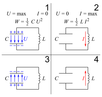
- At first, the coil is without magnetic flux. The capacitor is charged and the entire energy of the oscillating circuit is stored in its electric field. No current is flowing through the coil yet. (Figure 1)
- Due to the voltage at the capacitor, which also drops at the coil, current flow starts, but not abruptly increasing. According to Lenz's rule, a change in the current flow induces a voltage that counteracts its change. Thus, the current intensity and the magnetic flux increase only slowly (initially linearly with time). As the current increases, charge is removed from the capacitor over time, causing its voltage to decrease at the same time. As the voltage decreases, the increase in current flow decreases.
- When the voltage has dropped to zero, the current no longer increases and thus reaches its maximum. At this point, the magnetic field strength of the coil is also at its maximum and the capacitor is completely discharged. All the energy is now stored in the magnetic field of the coil. (Figure 2)
- When the coil is voltage-free, the current continues to flow steadily, since it cannot change abruptly - just like the magnetic flux. The current begins to charge the capacitor in the opposite direction. This causes a reverse voltage to build up in it (initially linear with time). This voltage, which increases with a negative sign, is equal to a voltage in the coil, which, according to the rules of induction, reduces the magnetic flux over time, which simultaneously reduces the current strength. With the reduction of the current flow, the charging of the capacitor and the increase of its negative voltage slows down.
- When the current is reduced to zero, the magnitude of the voltage no longer increases and thus reaches its maximum. The capacitor regains its original charge, but with the opposite polarity. All the magnetic field energy has been converted back into electric field energy. (Figure 3)
- These processes continue in the opposite direction. (Picture 4, then again picture 1)
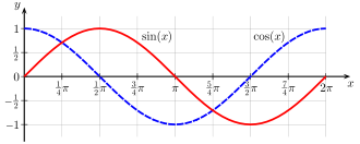
With continuous repetition, the voltage curve is set according to the cosine function; the current curve follows the sine function. The transition from Fig. 1 to Fig. 2 corresponds in the functions to the range x = 0 ... π/2; the transition from Fig. 2 to Fig. 3 runs as in the range x = π/2 ... π, from Fig. 3 via Fig. 4 to Fig. 1 as in x = π ... 2π.

U : voltage; I: current; W: energy

Voltage curve (blue dashed line) and current curve (red line) in the oscillating circuit
Free oscillations in the real series oscillating circuit
As a first approximation, the losses occurring in the real resonant circuit can be represented by an ohmic resistor R, which is in series with the inductance L. Based on the mesh theorem and the behaviour of the three components (and the assumption that current and voltage arrows all have the same direction of circulation), such an RLC series resonant circuit can be described by the following (linear) differential equation system (in state form with the capacitor voltage uC and the coil current i as state variables):
If one is only interested in the current in the oscillating circuit, then one can (by eliminating uC) transform this DGL system into a single linear differential equation of second order:
If, for the sake of simplification and generalization, the "abbreviations" for the (ideal) resonant circuit frequency
and the decay constant
one obtains the differential equation
The differential equation for the capacitor voltage has the same form. For the two initial conditions required for the unambiguous solution, it is usually assumed that at time t=0 the capacitor is charged with a voltage UC0 and the current through the inductance is 0.
Real resonant circuit
In general, a real resonant circuit can be described by the damped harmonic oscillator model. If one assumes that the losses in the oscillating circuit are small, specifically that δ 
then, using the classical methods for solving a linear homogeneous differential equation, using the Laplace transformation, or using some other operator calculus, one obtains the solution functions for the two state variables
Where φ 
In this "normal case of practice", current and capacitor voltage are 
Ideal resonant circuit
For the ideal case of a resonant circuit without losses, δ 
Aperiodic limiting case
If the losses are larger, then in the special case δ 
Creep
If δ 
then the following applies to the current
Search within the encyclopedia


