
Gear: design, types, materials, history and common uses
An overview of gears: definition, design principles, major types, materials, manufacturing methods, history, applications and common maintenance and selection considerations.
A gear is a rotating machine element with teeth that mesh with the teeth of a partner to transmit torque, change speed, alter direction of motion, or convert between rotary and linear movement. Gears are often called toothed wheels, cogs, or cogwheels. They appear in mechanisms ranging from simple mechanical clocks to complex automotive and industrial transmissions.
Image gallery
10 Images



Design and key characteristics
Important design features include tooth profile, size, spacing and orientation. Terms commonly used are pitch (spacing between teeth), module or diametral pitch (tooth size scales), pressure angle (influences load distribution and contact forces) and backlash (intentional clearance to allow lubrication and thermal growth). The involute tooth profile is widely used because it preserves a constant velocity ratio between mating gears despite small center distance variations. Gear ratio, defined by the relative number of teeth, determines speed and torque conversion.
Major types
- Spur gears: teeth parallel to the axis; simple, cost-effective, and suitable for moderate speeds and loads.
- Helical gears: angled teeth that engage gradually for smoother, quieter operation and higher load capacity.
- Bevel gears: conical wheels that transmit motion between intersecting axes, commonly at right angles.
- Worm gears: a screw-like worm meshing with a worm wheel for large reduction ratios and compact layouts; some arrangements exhibit self-locking under certain conditions.
- Rack and pinion: a gear (pinion) engaging a straight toothed member (rack) to convert rotary to linear motion.
- Planetary (epicyclic) sets: compact assemblies with multiple gear elements providing high torque density and multiple ratios used in automatic transmissions and industrial drives.
Materials and manufacturing
Gears are manufactured from a range of materials selected for strength, wear resistance, noise, cost and operating environment. Common materials include steels for high strength and toughness, nonferrous alloys for corrosion resistance and lighter weight, cast irons for damping and machinability, and engineered plastics for low-noise, low-load or cost-sensitive applications. Manufacturing processes include blanking or casting, followed by gear cutting methods such as hobbing, shaping and broaching; finishing operations can include heat treatment, grinding and surface hardening. Powder metallurgy and additive manufacturing are used for complex geometries or high-volume, cost-sensitive production.
History and development
Gears have been used since antiquity in water-lifting devices, astronomical instruments, clocks and early machines. Over centuries, materials and tooth forms evolved from wood and simple metal teeth to standardized involute profiles and precision-cut metal gears. Advances in metallurgy, heat treatment, machining, tribology and design theory enabled modern high-performance gears used in engines, automotive transmissions, robotics and industrial equipment.
Applications, maintenance and standards
Gears are essential in automotive drivetrains, bicycles, watches, machine tools, conveyors, robotics and power generation. They differ from related elements: a gear meshes with another gear, a sprocket engages a chain, and a pulley guides a belt. Proper lubrication, correct alignment, appropriate material selection and routine inspection are critical to gear life. Common failure modes include wear, pitting, scuffing, and tooth breakage; design choices, surface treatments and lubricants help mitigate these issues. Industry standards and terminology help ensure interchangeability and reliable performance; for basic definitions see gear terminology and for material considerations consult resources on nonferrous alloys, cast irons, plastic materials and specifications for steel gears.
Selection considerations and basic calculations
When selecting gears for a design, engineers consider required torque and speed, space constraints, noise, expected life, cost and lubrication. Basic calculations involve gear ratio, center distance, tooth geometry and contact stresses. While detailed design requires standards and tools, understanding these fundamentals helps in choosing the right type and material for an intended application.
Further reading
For practical guidance and standards consult technical handbooks and manufacturing references that cover gear geometry, materials, heat treatment, surface finishing and lubrication practices. Useful entry points include introductory material glossaries and manufacturer data sheets available via industry sources and standards organizations.


General
The wheels of a gear train rotate together with the shafts on which they are mounted, or rotate on axles on which they are supported.
The wheel spacing is designed so that the teeth mesh, and thus the rotary motion of one gear is transmitted to the other. When two gears with external teeth are paired, the direction of rotation is reversed. If this is not desired, a third gear of any size is placed between them. If the gears are of different sizes, the speed is increased or decreased, with the torque being reduced or increased (change in transmission ratio).
Types gears
Spur gear
→ Main article: Spur gear
The spur gear (or cylindrical gear) is the most commonly used gear. A cylindrical disc is toothed on its circumference. If the mating gear is also a spur gear or a spur-toothed shaft, the axes of the two gears are parallel and a spur gear is formed. However, spur gears are also used in gears with crossing axes, such as worm gears and crown gears. In addition to the spur gear as an external gear, there is also the internal gear, which is not referred to as a spur gear, since spur refers to an external shape.
There are straight (axis-parallel) splines, helical splines, double helical splines and various curved splines. In the case of double helical gears, a distinction is made between those with undercut and those without as true arrow gears.
Rack
→ Main article: Rack and pinion
The rack can be imagined as a spur gear with an infinitely large diameter. The pairing of a rack with a spur gear is called a rack-and-pinion gear. The movement of the rack is rectilinear and limited by its finite length. In common applications, a reciprocating motion takes place.
An unusually long rack, made up of many individual pieces, is the toothed rail of a rack railway.
Elliptical wheel
Most gear drives consist of round gear wheels or wheel bodies with round rolling lines. If the driving wheel rotates evenly, the driven wheel will also rotate evenly. An example of a gear transmission with an uneven transmission ratio, and thus consisting of non-circular gears, is an elliptical gear transmission. An elliptical gear is a non-circular gear.
If two elliptical wheels of the same size are combined, the centre distance is constant. The wheels each rotate about one of their elliptical focal points. The transmission ratio varies over one revolution by the average value i = 1. If only one wheel is elliptical, then one wheel must be mounted on an oscillating axle. Such gears are used, for example, in weaving machines. Better known is an elliptical chainring in the chain drive of bicycles.
· Bevel gear and crown gear
· 
Bevel gearbox
· 
Crown gear: spindle gear (spur gear, top) and crown gear (bottom)
Bevel gear
→ Main article: Bevel gearbox
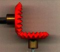
The axes of bevel gears are not parallel, but intersect. Most often, the angle of intersection is 90°. The basic shape is a truncated cone whose lateral surface is toothed. When two bevel gears are paired, their tips coincide. The teeth usually run straight in the direction of the generatrices, in the case of the so-called hypoid gear they are arc-shaped.
The tooth height profile of bevel gears corresponds to an octoid.
Spiral bevel gears are mainly distinguished as follows:
- Circular arc toothing with non-constant tooth height (manufacturer Gleason)
- Circular arc gearing with constant tooth height (Kurvex)
- Cyclo-palloid gearing (Klingelnberg)
- Palloid toothing (Klingelnberg)
Crown wheel
→ Main article: Crown wheel
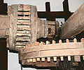
A crown gear is an angular gear and a variant to the bevel gear. It was used more often than a bevel gear in the past (see illustration: crown gear made of wood). In a crown gear, the teeth are located on the circular surface of a cylinder. Together with a spur gear, it forms a crown gear.
Worm wheel and worm
→ Main article: Worm gear
A worm gear formed by a worm wheel and worm is used in addition to other gears when the shafts cross but do not intersect. Another feature is the relatively high transmission ratio.
In the simplest case, the worm gear can be a helical gear. In order to achieve line contact instead of only point contact between the teeth in the gear, the tooth flanks of the worm gear are hollow.
The teeth on the small worm resemble a thread. The worm is more or less a spur gear with a few very oblique teeth wound helically around the barrel. One turn corresponds to one tooth. In the globoid worm, the thread-like teeth are not cylindrical. The cylinder is waisted and thus adapts to the curvature of the worm wheel.


Questions and answers
Q: What are gears?
A: Gears are mechanical parts with cut teeth designed to fit with teeth on another part so as to transmit or receive force and motion.
Q: What are some other names for gears?
A: Gears are also sometimes called toothed wheels or cogged wheels or cogs.
Q: What are the cut teeth on gears sometimes called?
A: The cut teeth on gears are also sometimes called cogs.
Q: What materials are used in the manufacture of gears?
A: Numerous nonferrous alloys, cast irons, powder-metallurgy and even plastics are used in the manufacture of gears.
Q: What is the most commonly used material in the manufacture of gears?
A: Steels are most commonly used in the manufacture of gears because of their high strength to weight ratio and high cost.
Q: Why are steels frequently used in the manufacture of gears?
A: Steels are frequently used in the manufacture of gears because of their high strength to weight ratio and high cost.
Q: What is the purpose of gears?
A: The purpose of gears is to transmit or receive force and motion.
Related articles
Author
AlegsaOnline.com Gear: design, types, materials, history and common uses Leandro Alegsa
URL: https://en.alegsaonline.com/art/37810