Flywheel — mechanical energy storage and rotational inertia
A flywheel is a rotating mass designed to store kinetic energy and stabilise rotational speed. This article covers principles, construction, applications, history, design trade-offs and safety considerations.
A flywheel is a rotating mass, typically a disk, ring or rim, engineered to store kinetic energy and to resist changes in rotational speed. It is mounted on a rotating shaft so energy can be absorbed from or delivered to connected machinery. The stored energy and the resistance to speed change arise from the rotor's angular momentum and from how its mass is distributed relative to the axis. Flywheels are used where torque delivery is intermittent or uneven, to smooth output, to recover braking energy and to supply brief bursts of power.
Image gallery
4 Images

Principle and key formulas
The kinetic energy held in a spinning flywheel is given by the general expression E = 1/2 I ω^2, where I is the moment of inertia and ω is the angular velocity. The moment of inertia depends on total mass and distribution: for a thin rim I is approximately M R^2, while for a solid disk I is approximately one half M R^2, where M is mass and R is radius. Because energy scales with the square of ω, increasing rotational speed is more effective than adding proportionally more mass, but higher speed demands stronger materials and containment. The rotor’s resistance to changes in rotation follows from conservation of angular momentum and is related to momentum in rotational form.
Construction, materials and bearings
Traditional flywheels are heavy steel or cast-iron disks with mass concentrated near the rim to maximise inertia. Modern high-performance rotors use high-strength alloys or carbon-fiber composites that enable much higher rotational speeds for a given mass, increasing energy per kilogram. Low-loss support is important: high-quality bearings, vacuum housings or magnetic bearings limit drag and friction losses, improving energy retention. Typical assemblies may include clutches, gears or power electronics to control connection between the flywheel and prime mover or load.
History and development
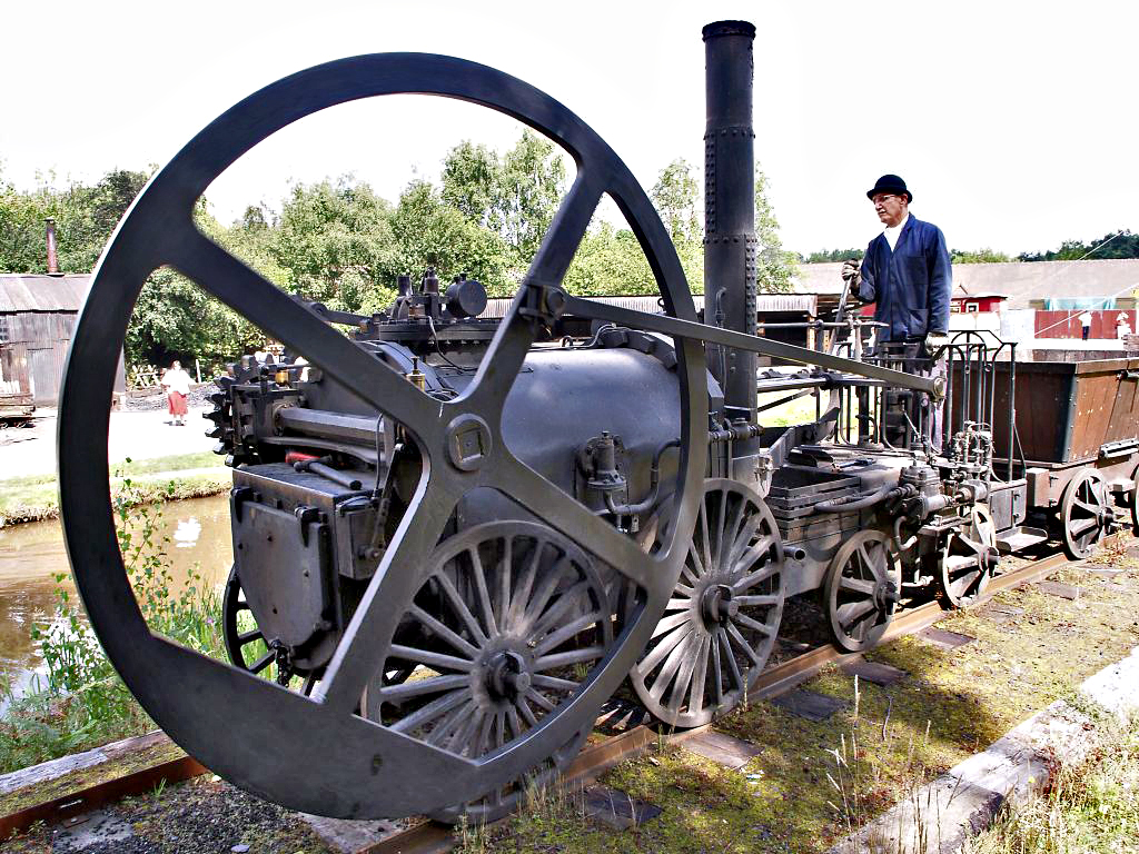
Analogues of the flywheel have existed for centuries in mills and clockwork to average irregular motion. During the industrial revolution flywheels were integral to steam engines and to early mechanical drive trains. Internal combustion engines with reciprocating pistons require flywheels to smooth the pulses of torque between combustion events. In the late 20th and early 21st centuries, advances in materials and bearings spawned flywheel energy storage systems for transportation and electrical-grid services.
Applications
- Automotive and transport: conventional engines use flywheels for smooth idling and to couple manual transmissions; some buses and trams have used flywheels to store braking energy for repeated stop-start cycles.
- Energy systems: grid-scale and microgrid prototypes use high-speed flywheels for short-duration energy buffering, frequency regulation and ride-through of transient faults.
- Industry: machine tools, presses and generators use flywheels to carry loads through torque fluctuations and to stabilise rotational speed.
- Specialised devices: gyroscopes and inertial navigation exploit similar spinning-rotor principles for attitude control and sensing.
Design trade-offs and safety
Designers balance three main factors when specifying a flywheel: total mass, radial size, and rotational speed. Adding mass increases stored energy but also increases structural load and wear on bearings; increasing radius increases inertia for the same mass distribution; increasing speed yields the greatest energy gain per unit mass but raises centrifugal stresses. High-speed rotors require rigorous containment and monitoring because a structural failure at high angular velocity can release stored energy violently. Fail-safe housings, sensors for imbalance and overspeed, and controlled shutdown are standard safeguards.
Practical notes
Flywheels are efficient for applications requiring many charge–discharge cycles and fast response, and they complement chemical batteries where short-term power or long cycle life is needed. When considering a flywheel, engineers account for coupling losses, bearing life, standby loss (self-discharge) and the dynamics of how energy is exchanged with an attached shaft or power electronics. For introductory topics see materials on disk and rim geometry and on kinetic energy, and consult specialist texts for detailed design of rotors, containment and integration with torque-producing machinery.

Applications
Energy storage
Applications include reciprocating engines, especially 1-cylinder four-stroke engines. These only have a power stroke every fourth half revolution, which transmits energy to the output via the crankshaft. In the remaining three strokes, they require energy to maintain rotary motion and compress the combustion air. The energy of the power stroke is temporarily stored in the flywheel and then continuously released again.
The simplest small toy vehicles do not require a spring mechanism and typically travel 3 m with flywheel drive alone. The flywheel consists of 1 to 3 punched circular discs with a diameter of 2 to 4 cm, made of 1 to 2 mm thick sheet iron, perforated and pressed onto a steel axle which is mounted in sheet metal or plastic.
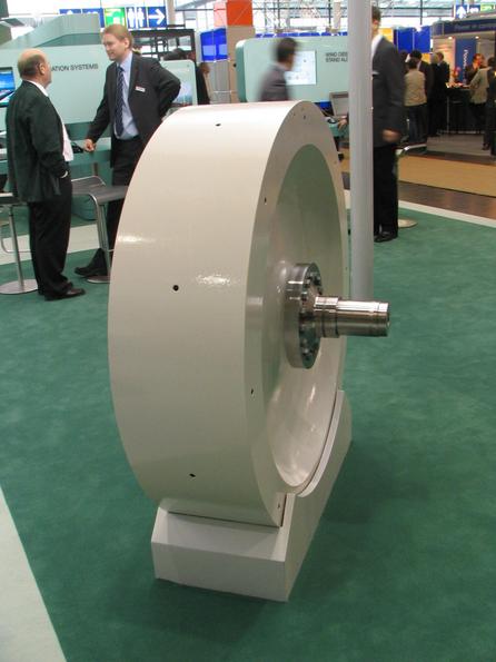
Another application is flywheel storage power plants in modular design for balancing sudden additional demand in electricity grids. For storage, a flywheel is driven by means of an electric motor and the energy is held in reserve in the form of rotational energy for energy output in the minute range.
The ASDEX Upgrade fusion experiment uses a flywheel generator weighing 400 tonnes, which takes a few minutes to ramp up from 800 to 3000 revolutions, and then calls up the stored energy within fractions of a second to heat up the plasma.
On the Norwegian island of Utsira, a self-sufficient power grid was established in 2004, whereby short-term power fluctuations are compensated by a flywheel storage (5 kWh). The flywheel masses of all turbines and generators running in the grid power production (synchronously) have a significance for the stabilization of the grid frequency, i.e. energy storage for the period of the order of magnitude of a phase of 1/50 second. Similarly, the flywheel mass of electric motors means for smoothing the torque output. Flywheels in large stationary machines can only store local mechanical amounts of energy, which are used up in pressing, forging, punching, rolling and cutting processes in typically half a second, in order to be supplied again by electric motors in several seconds afterwards.
Position stabilization
Rotating flywheels do not allow any angular changes of their axis. This is used for stabilisation, e.g. in gyrocompasses for ships and the devices in satellites known as swirl wheels or inertial wheels.
Rotational irregularity, torsional vibrations
In many dynamic processes on machines, rotational irregularities (fluctuations in speed) occur. These are caused by periodically occurring torques and can lead to torsional vibrations (=torsional oscillations). Flywheels reduce the rotational irregularity through their mass inertia by absorbing energy during acceleration and releasing it again during deceleration. The rotational irregularity is thus reduced. The disadvantage is that a large mass has to be set in motion, which means additional weight for vehicles. For this reason, attempts are usually made to keep the non-uniformity low (for example, in the case of internal combustion engines by means of several cylinders) or to reduce the torsional vibration itself in other ways (vibration damping).
A vibration damper consists of a flywheel mass and a damping element (e.g. oil or rubber), which transmits the vibration-damping forces between the flywheel mass and the component to be damped. The oscillating part "supports" itself, so to speak, via a damping element on the smoother-running flywheel mass. The damping element thereby converts kinetic energy into heat and thus extracts the kinetic energy (vibration energy) from the vibrating component.
A flywheel was used for vibration damping (actually: amplitude reduction) for the first time in the engine of the BMW R 69 S motorcycle from the 1960 model year onwards, in order to prevent the previously frequent crankshaft fractures due to vibrations in the highly loaded engine. Here, a small flywheel on the side opposite the clutch at the front of the engine ensured less rotational irregularity of the oscillating crankshaft-flywheel-clutch system.
A similar special form of flywheel in passenger cars is the so-called dual-mass flywheel. Here, the use of a primary and a secondary flywheel mass with an elastic element in between greatly reduces the transmission of engine vibrations to the rest of the driveline (e.g. transmission idle rattle). The primary and secondary flywheel masses are separated from each other by a precisely matched spring/damper system. The flywheel mass on the transmission side (secondary flywheel mass) is heavier than the flywheel mass on the engine side (primary flywheel mass). This increases the mass moment of inertia of the gearbox, which greatly reduces the non-uniformity, especially at low speeds. The torsional vibration excitation acting on the drive train is greatly reduced.
The balance of the mechanical watch, in conjunction with the hairspring, represents a rotary oscillator, the period of which is highly constant (isochronism).


History
Antiquity and Middle Ages
Mass inertia in the form of rotating masses was already used in ancient times. Spinning whorls made of clay or stone have been documented since the early Neolithic, e.g. in Achilleion. Simple flywheels were also used in potter's wheels to ensure continuous, uninterrupted and even rotation.
In the Middle Ages, wooden flywheels already had speeds of around 100 revolutions per minute and could maintain rotation for several minutes in some cases. The flywheel as a general machine element for storing kinetic energy is first found in the De diversibus artibus (On Various Arts) by Theophilus Presbyter (ca. 1070-1125), who used it in several of his machines.
Modern Times
Flywheels are used to compensate for the non-constant torque in steam engines and internal combustion engines. Short-term load peaks in working machines can be compensated by flywheels and the energy stored in them and often allow a significantly smaller drive motor, e.g. in generator sets to cover the often very high starting currents in electric motors.
Flywheels were also used in early helicopter development. In 1927, in contrast to the hydrofoils and helicopters known up to that time, the rotors of the Zaschka rotary aircraft were connected by chief engineer Engelbert Zaschka with a flywheel mass acting on two gyroscopes in a forcibly rotating manner. This arrangement made it possible to perform a safe vertical glide with the engine switched off.
In the 1950s, so-called gyrobuses were in use in Basel in Switzerland as well as in Austria. In 1955, a fleet of 12 gyrobuses was operated in Leopoldsville (then Belgian Congo). The flywheels came from Maschinenfabrik Oerlikon and offered the possibility of regenerative braking. In the 1990s, buses with flywheel accumulators were used in Munich and Bremen. These buses drew their energy for the electric drive exclusively from a flywheel (storage capacity 9.15 kWh). They could travel about 20 kilometers without being connected to the power grid. Then they had to dock with the power grid at each stop to recharge the flywheel. This type of energy storage did not prove successful at the time, partly because of technical inadequacies. Today's flywheels work with magnetic bearings and almost no friction in vacuum housings.


Questions and answers
Q: What is a flywheel?
A: A flywheel is a heavy disk or wheel that is attached to a rotating shaft. It is used for storage of kinetic energy and helps keep the shaft rotating at the same speed by resisting changes in speed due to uneven torque.
Q: How does a flywheel store energy?
A: A flywheel stores energy by taking it from the wheel when it rotates, and then releasing it again when energy is needed. The amount of energy stored depends on its mass, angular velocity, and radius.
Q: What are some applications of flywheels?
A: Flywheels are used in engines which use pistons to provide power as they help fix the problem of uneven torque changing the speed of rotation. They are also used in buses for stopping and starting, where rotational energy from the wheels is transferred to the flywheel so that it can slow down while speeding up.
Q: What factors affect how much energy a flywheel can store?
A: The amount of energy stored in a flywheel depends on its mass, angular velocity, and radius. Heavier weights with faster speeds require more energy to rotate them than lighter weights with slower speeds.
Q: Are all wheels considered "flywheels"?
A: No, not all wheels are considered "flywheels". Flywheels are specifically designed for storing kinetic energy and should be heavy or rotate fast in order to do this effectively.
Q: How does a bus use a flywheel?
A: Buses use flywheels by connecting them to their wheels when they stop (e.g., at traffic lights). This transfers rotational energy from the wheels to the flywheel so that it can slow down while speeding up again when starting back up again later on.
Related articles
Author
AlegsaOnline.com Flywheel — mechanical energy storage and rotational inertia Leandro Alegsa
URL: https://en.alegsaonline.com/art/35315