
Electrical impedance: definition, representations, frequency behaviour and applications
Comprehensive overview of electrical impedance: definition, complex and polar forms, component formulas, frequency dependence, energy behaviour, reflection and practical applications.
Electrical impedance is the quantity that describes how an electrical network or component opposes the flow of alternating current and the change of voltage. It generalizes the concept of resistance to situations where voltage and current vary in time, and it combines both the in‑phase opposition associated with resistors and the phase‑shifting opposition associated with inductors and capacitors. In practice impedance is a complex number and can be handled algebraically in the same way as other phasor quantities. Current and voltage behaviour are linked by impedance in the same role that resistance plays for steady direct current.
Image gallery
2 Images
Representation and basic properties
Impedance is conventionally denoted by Z and measured in ohms (symbol Ω). There are two equivalent ways to express a complex impedance: rectangular form and polar form. In rectangular form Z = R + jX, where R is the real part (resistance) and X is the imaginary part (reactance). The same quantity can be written in polar form as Z = |Z| ∠θ, where |Z| is the magnitude and θ is the phase angle between voltage and current. These two forms are related by simple algebra and trigonometry and are useful in different contexts; rectangular form makes series and parallel algebra easier, while polar form makes multiplication and division straightforward. Real part and imaginary part terminology is common in circuit analysis.
Component impedances and frequency dependence
Impedance varies with frequency for reactive components. A pure resistor has the same impedance at all frequencies and dissipates energy as heat. An ideal inductor has an impedance that increases linearly with frequency: Z_L = j 2π f L, where L is inductance and f is frequency; this causes the inductor to resist rapid changes in current. An ideal capacitor has impedance that decreases with frequency: Z_C = 1 / (j 2π f C), where C is capacitance; this makes a capacitor resist changes in voltage most at low frequencies. At the limits, an inductor looks like a short circuit at DC (zero hertz) while a capacitor looks like an open circuit. These frequency formulas are central to designing filters, oscillators and tuned circuits. Frequency and its role in impedance are often handled using phasor methods or the Fourier transform for non‑sinusoidal signals. Fourier techniques decompose complex waveforms into sinusoids, each of which sees a different impedance.
Energy: dissipation versus storage
Resistance and impedance differ in how they interact with energy. A resistor converts electrical energy to heat and thus dissipates power. Inductors and capacitors, by contrast, store energy temporarily — an inductor in its magnetic field and a capacitor in its electric field — and can return that energy to the circuit. This exchange leads to phase differences between voltage and current: in a pure inductor the current lags the voltage by 90°, while in a pure capacitor the current leads by 90°. The physical origins are commonly described in terms of electron collisions for resistive losses and field creation for reactive behaviour. Physical intuition helps when interpreting transient responses and resonance.
Impedance matching and reflections
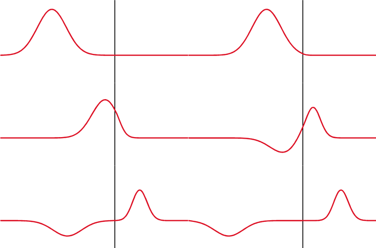
When energy is transferred between stages, such as a source, a cable and a load, mismatches in impedance cause part of the wave to be reflected back toward the source. The amount of reflection at a boundary between impedances Z_S (source) and Z_L (load) is described by the reflection coefficient Γ = (Z_L − Z_S) / (Z_L + Z_S). Minimizing reflections by matching impedances maximizes power transfer and reduces interference in radio‑frequency, microwave and high‑speed digital systems. Transmission line theory introduces a characteristic or wave impedance for a medium; even free space has a characteristic wave impedance (approximately 377 Ω for electromagnetic waves in vacuum). Understanding wave impedance is crucial in antenna design, cable engineering and optical systems. Resistance vs impedance, DC limits and the reflection formula are routine tools for engineers.
Applications, measurement and practical notes
Impedance is a fundamental concept across electrical engineering: it determines speaker and microphone loading in audio systems, sets filter behaviour in analog electronics, governs matching in RF and microwave circuits, and influences signal integrity in digital interconnects. Measuring impedance can be done with impedance bridges, vector network analyzers or LCR meters that report magnitude and phase or real and imaginary components. Practical circuits often include complex combinations of resistors, capacitors and inductors; at higher frequencies parasitic capacitances and inductances of components and interconnects become significant and must be modeled as part of the overall impedance. Standard analysis techniques include phasor algebra for linear steady‑state problems and Laplace methods for transient responses. Resistors, inductors and capacitors remain the building blocks but real designs must account for non‑ideal behaviour and frequency dependence. Wave concepts tie circuit impedance to broader electromagnetic theory.
- Key formulas: V = Z·I relates phasor voltage and current; Z_R = R, Z_L = j2πfL, Z_C = 1/(j2πfC).
- Two common forms: rectangular Z = R + jX and polar Z = |Z| ∠θ.
- Match impedances to reduce reflections and maximize power transfer; use Γ = (Z_L − Z_S)/(Z_L + Z_S) to quantify mismatch.
For further structured tutorials and reference material on these concepts, review introductory and advanced resources in circuit analysis and electromagnetic theory. Many textbooks and laboratory guides illustrate impedance with circuit examples, frequency sweeps and network measurements that reinforce the relationships summarized here. Magnitude and phase are practical outputs of most test instruments, and clear visualization of the complex impedance plane can aid both design and troubleshooting. Voltage–current relationships and the historical development of alternating‑current theory provide useful background for students and practitioners alike. Voltage and the behaviour of reactive components remain central to modern electronics.
Questions and answers
Q: What is electrical impedance?
A: Electrical impedance is the amount of opposition that a circuit presents to current or voltage change.
Q: How can electrical impedance be written?
A: Electrical impedance can be written with the resistance "R" (real part) and the reactance "X" (imaginary part), as well as with a magnitude, phase, size, and angle.
Q: What is the difference between resistance and impedance?
A: The key difference between resistance and impedance is the word "change"; in other words, the rate of change affects the impedance. Resistance resists any current going through it while an inductor resists changes to the current and a capacitor resists changes to the voltage.
Q: What are some formulas associated with resistance and impedance?
A: For resistance, V=R*I where V is voltage, R is resistance, and I is current; for inductors Z=j2πfL; for capacitors Z=1/j2πfC; where Z represents impedance, j represents imaginary number -1 , π represents constant pi, f represents frequency, L represents inductance, C represents capacitance.
Q: What are some physical explanations for resistance vs. impedance?
A: Resistance is caused by electrons colliding with atoms inside resistors while an inductor's impedance comes from creating an electric field and a capacitor's comes from creating a magnetic field. Additionally, resistors dissipate energy while inductors and capacitors store energy which can then be returned to source when it goes down.
Q: How do you calculate reflection coefficient?
A: Reflection coefficient can be calculated using Γ=(ZL-ZS)/(ZL+ZS) where Γ (capital gamma) stands for reflection coefficient; ZS stands for source's impedence; ZL stands for load's impedence
Related articles
Author
AlegsaOnline.com Electrical impedance: definition, representations, frequency behaviour and applications Leandro Alegsa
URL: https://en.alegsaonline.com/art/30700