
Control system: principles, types, and practical applications
An overview of control systems: definition, elements, open- and closed-loop distinctions, common algorithms, history, and typical uses in industry, vehicles, robotics and electronics.
A control system is an arrangement that issues commands to direct the behavior of other devices or processes. At its core a control system senses the state of a process, compares that state with a desired goal, and sends corrective signals to actuators. In engineering practice the term can refer to a single device that enforces a setpoint or to a larger system that coordinates multiple machines.
Image gallery
5 Images
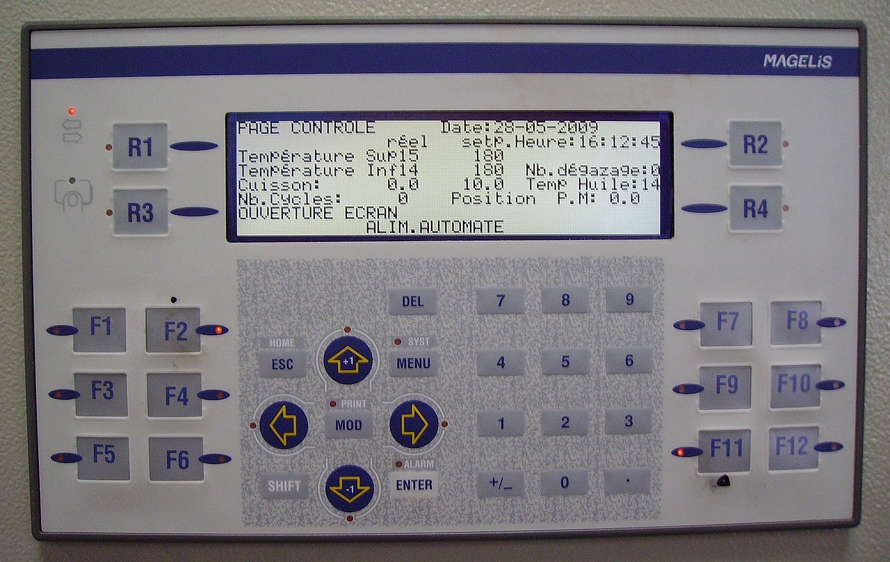


Fundamental elements
Most control systems include sensors, a decision-making element (controller), and actuators. The controller computes commands from measured inputs and programmed objectives. Simple instances use fixed rules, while advanced designs employ adaptive or model-based algorithms. The relationship between the input and the resulting behavior is often captured in a transfer function or a block diagram, sometimes called a logic diagram.
Types and notable algorithms
- Open-loop control: commands are issued without feedback and depend only on known inputs, useful when disturbance is small.
- Closed-loop (feedback) control: measures output and corrects errors; this class includes PID controllers, a widely used standard for industrial regulation.
- Adaptive and robust controllers: adjust parameters in real time to cope with changing conditions.
Control strategies can be implemented by hardwired electronics, programmable logic controllers, or software running on embedded computers. Commands may be manually set or programmed, and the observed output is a function of the chosen inputs and the environment. Designers study stability, responsiveness, and accuracy when tuning a system.
History and applications
Ideas of feedback date back to early mechanical regulators such as the centrifugal governor; later formal study in the 20th century led to modern control theory. Today control systems appear in heating thermostats, industrial automation, aircraft autopilots, automotive cruise control, robotics, and consumer electronics. They coordinate sensing, computation, and actuation to achieve reliable performance.
Practical design balances complexity and robustness. Engineers choose sensors and actuators appropriate to the task, create models to predict responses, and use simulation and experimentation to validate behavior. For introductions and deeper treatment see standard texts or online resources represented here as further material and tutorials at manufacturer pages or educational repositories under course links.

Control loops outside the technology
Biological control circuits
The term "control loop" is used in biology to describe processes in living organisms for the maintenance of homeostasis. Control loops are therefore not always purely technical models, but a general organisational principle that can also be understood under terms such as self-regulation and systems theory. There are both relatively simple and more complex ones at the physiological level within the organ systems of higher organisms that contribute to their homeostasis through negative feedback, up to the highly complex control loops within communities at the level of ecology. Examples:
- End product inhibition of enzyme activity in cells and tissues.
- Regulation of the water balance in plants
- Regulation of respiration (a humoral control circuit based on chemoreceptors)
- Regulation of the oxygen content of the blood
- Thermoregulation: Animals at the same temperature require a certain body temperature for survival, which varies within a tolerance band, but should not leave this band. The nervous system of every animal of the same temperature therefore contains a temperature control circuit with corresponding receptors as sensors, and blood vessels that can dilate and constrict, as well as muscles as regulators, in humans also variable transpiration.
- Regulation of the water balance and the acid-base balance by the kidney
- Pulse regulation: For the adequate supply of the cells with oxygen and energy, sufficient blood circulation is required, which depends on the physical load. This is ensured, among other things, by the regulation of the heart rate and the cardiac output by the autonomic nervous system.
- Blood pressure regulation: If the blood pressure is too low, sufficient blood circulation and supply of the cells with oxygen and energy is not possible. Too high blood pressure damages the organs. Therefore, there is a blood pressure regulation in animals and humans.
- Regulation of the amount of light entering the eye by enlarging or reducing the pupil and the adaptation of other sensory organs (Weber-Fechner law).
- Regulation of the blood level of numerous hormones (e.g. in the thyrotropic control circuit)
- Regulation of food intake through hunger and satiety
- Regulation of the blood sugar level: The blood sugar ensures the energy supply of the organism and is adapted to the physical strain.
- Regulation of population density through predator-prey relationships
- There is also a control loop in species protection; the target value here is the favourable conservation status of populations.
See also: Biological cybernetics
Economic control loops
From the field of economics, the following should be mentioned:
- market pricing
- Market regulation of the state.
- spider web theorem, pig cycle
Management-oriented control loops
- management cycle
- Control loop of personnel management
Quality Circle
In the area of quality management, there is the quality circle, on which quality management systems are based in accordance with the DIN EN ISO 9001:2015 regulations.
Linguistic control circuits
In the article Linguistic Synergetics it is shown that Quantitative Linguistics has developed control circuits on different language levels (morphology(linguistics), writing, syntax and others), which partly also act beyond the language levels or connect them with each other.

Control loops in technology
Introduction
A real control loop consists of several individual components of the controlled system and the controller, each of which has a specific time response. While the controlled system is usually available as a technical system, a system analysis of the controlled system is required for the mathematical treatment of the closed loop, from which a mathematical model can be determined. The model should largely correspond to the time response of the real controlled system. The observation of a signal course at a transmission system for a given input signal  starts at
  and ends for the course of the output signal
  with
with  .
.
In conjunction with the controlled system model  , a controller
  be parameterized, which ensures stability for the closed loop according to the closing condition
 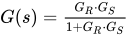 . In general, the parameters of the controller cannot be adjusted optimally by hand for more complicated controlled systems. Industrial control processes with controller mismatches can cause destruction of equipment due to amplitude build-up of the controlled variable.
Modern electronics allow the realization of arbitrarily complex controller structures with justifiable economic expenditure. In many cases, digital controllers are used instead of analog controllers and may be combined with digital measuring and control elements. The digital signals are value and time discrete signals. These control loops behave like analog control loops if the resolution and sampling rate are high enough.
For the design of a controller in engineering, the mathematical model of the controlled system is required. For multivariable systems (MIMO) the controller design with the state space representation is suitable, for nonlinear and dead-time single-variable systems (SISO) the numerical calculation is recommended. The classical graphical controller design methods (Bode diagram, locus of frequency response, root locus method) have only didactic informative significance.
The most common mathematical system descriptions are the differential equation  , the transfer function
  , the frequency response
  and the discrete-time difference equation
 ![{\displaystyle y(k)=y(k-1)+f\,[u(k),\,System]}](https://www.alegsaonline.com/image/140a5613af62de04238f567f08aca7501f19c124.svg) .
.
The aim of the mathematical descriptions of control loop elements is the calculation of the dynamic input and output behaviour of individual components, closed control loops and their stability.
Due to required quality criteria (control quality) of the transient process of the controlled variable, the heuristic method "trial and error" is usually used in the offline simulation of the control loop.
Simulation of the input and output behaviour of a control loop
Unfortunately, individual components of most technical controlled systems behave non-linearly. The transfer function and its algebraic calculation may only be used for linear transfer systems.
If, for example, the controlled system contains a dead time (transport time), limiting effects of some components or other non-linearities, the discrete-time calculation of the control loop with difference equations is practically the only option for the system calculation. The open control loop is closed by the relation  as input variable of the controller, which determines the desired behavior of the control loop with its time response.
Difference equations or a chain of difference equations describing several elementary systems connected in series let the output quantity  calculated
  algebraically for a small time step Δ
  depending on the input signal The numerical overall solution of the system is - in the case of simple difference equations - done recursively over many computational sequences, each in small constant time intervals. The form of the overall solution is thus tabular.
The typical form of a recursive difference equation of common control loop elements (linear factors) is:
![{\displaystyle y(k)=y(k-1)\,+f\,[u(k),\,\Delta t,\,T]}](https://www.alegsaonline.com/image/7a3357e7cf11cec7727fc8d5e524aee4843d76e3.svg) .
.
Where  . The sequence
  describes a finite number of the sequence members.
Difference equations of the linear time-dependent system components can be derived from ordinary differential equations by replacing the differential quotients by difference quotients Δ .  Nonlinear transfer systems can be described, for example, by logical statements such as IF-THEN-ELSE statements or tables.
 See article difference equation.
Digital controllers
Digital control means that the input signal of a dynamic system or a subsystem is sampled at specific discrete points in time, calculated synchronously in time and output as a digital output signal. Other terms refer to this process as "discrete-time control" or also as "sampling control".
Digital controllers are implemented by microcomputers. They process difference equations suitable for the desired control behavior of the overall system.
Since the controlled systems are mostly given analog systems, the interface of the system requires an analog input signal via a DA converter.
Advantages: One-time hardware development effort, easy parametric system changes via software, realization of more complex controller structures, multitasking.
Disadvantages: The use of a digital controller is only worthwhile for larger production quantities due to the increased technical effort.
See article Digital controller, Z-transform and difference equation.

Related articles
Author
AlegsaOnline.com Control system: principles, types, and practical applications Leandro Alegsa
URL: https://en.alegsaonline.com/art/22804