
Capacitance: definition, principles, history, and practical uses
Capacitance measures an object's ability to store electric charge per unit voltage. This article explains basic formulas, physical origins, common types of capacitors, and typical applications.
Overview
Capacitance is a fundamental electrical property that quantifies how much electric charge a body can hold for a given electric potential (voltage). It is defined by the ratio C = Q/V, where Q is stored charge and V is the potential difference. The SI unit of capacitance is the farad, named after Michael Faraday. For a general introduction, see capacitance overview.
Image gallery
2 Images

Physical basis and formulas
At a microscopic level, capacitance arises because separated conductors can hold equal and opposite charges while an insulating medium (a dielectric) reduces the electric field between them. For simple geometries there are closed-form expressions: the parallel-plate capacitor has C = εA/d, where A is plate area, d the separation, and ε the permittivity of the dielectric. The energy stored in a capacitor is given by E = 1/2 C V2, which makes capacitors useful as temporary energy reservoirs.
Types and characteristics
Capacitance can refer to a single conductor's self-capacitance or the mutual capacitance between two conductors. Practical devices called capacitors vary by dielectric and construction: electrolytic, ceramic, film, tantalum and supercapacitors each trade off capacitance per volume, voltage rating, stability, and cost. Key characteristics include capacitance value, tolerance, working voltage, equivalent series resistance (ESR), and temperature coefficient.
History and naming
The concept developed in the 19th century alongside studies of electrostatics. Its name and the SI unit honor Michael Faraday for his experimental work on electricity and electrochemistry. Modern component manufacturing expanded the range of available capacitances and introduced specialized types such as double-layer "supercapacitors" for high energy density.
Uses and examples
Capacitors are ubiquitous in electronic circuits: they smooth power supplies, filter signals, set timing intervals in oscillators, and couple or decouple AC and DC components. Large banks of capacitors are used for power-factor correction in industrial systems, while supercapacitors provide short-term backup or regenerative-energy capture. For details on capacitors as components, see capacitor types.
Notable facts and distinctions
- The farad is a large unit: most electronic capacitors are measured in microfarads (µF), nanofarads (nF) or picofarads (pF). For information on units, consult SI units and the farad.
- Dielectrics not only increase capacitance but influence leakage and breakdown voltage.
- Capacitance is a linear property for ideal components (Q proportional to V) but real devices can show voltage-dependent or frequency-dependent behavior.
Understanding capacitance connects electrostatics and practical circuit design: its simple definition belies a wide range of phenomena and engineering trade-offs.
Capacitance of a capacitor
Capacitance has a technical application in the form of electrical capacitors, which are characterized by the specification of a certain capacitance. The term "capacitance" is also used colloquially as a synonym for the electrical component capacitor itself.
Capacitors represent a conductor arrangement with two electrodes for separate storage of electric charge  and
and  In physical terms, the electric flow stems
  from the separated electric charges and transported to the electrodes by the external voltage source with voltage
  , thus:

results. Formally, this relationship takes place via Gauss' law. The electrical capacitance of a capacitor can then be expressed as the ratio of the quantity of charge  to the applied voltage
 .
.
Here,  usually a constant parameter that is obtained as follows.
A body to which a positive electric charge is given thereby has an electric field which opposes the movement of another positive electric charge towards the body. However, if there is now a body nearby that is negatively charged, the repulsive electric field of the positive body is weakened (the positive charge moving towards the body also feels the force of the attracting negative charge). Thus, less voltage is needed to move the additional positive charge onto the already positively charged body than without the second negatively charged body. So the first body has a higher capacity. Of course, the same is true for the second body. The attenuation of the electric field through one charged body to the other charged body is influenced by their geometry and the permittivity of the insulating medium between the two bodies.
In a simplified analogy, the capacity corresponds to the volume of a compressed air tank with constant temperature. The air pressure is analogous to the voltage and the amount of air is analogous to the amount of charge . Therefore, the amount of charge in the capacitor is proportional to the voltage.
This law also applies to the so-called pseudocapacitance, an electrochemical or faraday storage of electrical energy that is voltage-dependent within narrow limits and is associated with a redox reaction and charge exchange at the electrodes of supercapacitors, although unlike accumulators, no chemical change occurs at the electrodes.
Among others, the Physikalisch-Technische Bundesanstalt (PTB) deals with capacitance standards.
Unit
Electrical capacitance is measured in the derived SI unit farad. A farad (1 F) is the capacitance that stores an amount of charge equal to 1 coulomb (1 C = 1 As) when a voltage of 1 volt is applied:
![[C]=\frac{[Q]}{[U]} = \frac{1\,\mathrm{C}}{1\,\mathrm{V}} = \frac{1\,\mathrm{As}}{1\,\mathrm{V}} = 1\,\mathrm{F}](https://www.alegsaonline.com/image/4cfe58eeb914791a0546e3cf20f16ce90a579d18.svg)
A capacitor with a capacity of 1 farad charges to a voltage of 1 volt in 1 second at a constant charging current of 1 ampere. The SI unit Farad, named in honor of the English physicist and chemist Michael Faraday, has now become internationally accepted everywhere.
Obsolete unit
Until the middle of the 20th century, the capacitance of capacitors was often labeled with the unit of capacitance cm. This indication in centimeters is due to the fact that the capacitance is expressed in the length dimension in the Gaussian system of units, which is practically no longer used today. Thus, a metal sphere with a radius of 5 cm has a capacitance of 5 cm compared to a counter electrode located at infinity.
The adjacent figure shows a paper capacitor of the SATOR brand of the former Kremenezky, Mayer & Co company from 1950 with a capacitance of 5000 cm. This corresponds to the capacitance of a metal sphere of 5000 cm radius. Represented in today's SI system of units, this is approx. 5.6 nF.
A capacitance of 1 cm in the Gaussian system of units is equivalent to about 1.1 pF in the SI system of units, and the conversion factor is 4πε0. This conversion comes about because of the definition of the field constant in the Gaussian system of units:
 in the Gaussian system of units (not in the International System of Units (SI)).

Capacitance of certain conductor arrangements
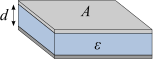
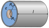
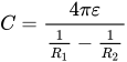
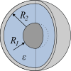
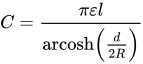
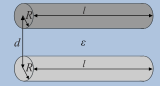
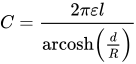
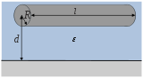
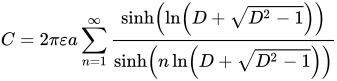
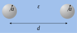
For the capacitance of a series of simple ladder arrangements, there are analytical solutions or convergent series expansions. The following table shows some examples:
| Designation | Capacity | Schematic representation |
| Plate capacitor |
|
|
| Coaxial cable or cylindrical capacitor |
|
|
| Spherical capacitor |
|
|
| Sphere, counter electrode with |
| |
| Parallel cylinder |
|
|
| A conductor in parallel over a |
|
|
| Two spheres with identicalradius |
|
|
| Circular diskagainst |
|
|
| Straight wire piece |
|
|









![{\displaystyle C={\frac {2\pi \varepsilon l}{\Lambda }}\left\{1+{\frac {1}{\Lambda }}\left(1-\ln 2\right)+{\frac {1}{\Lambda ^{2}}}\left[1+\left(1-\ln 2\right)^{2}-{\frac {\pi ^{2}}{12}}\right]+{\mathcal {O}}\left({\frac {1}{\Lambda ^{3}}}\right)\right\}}](https://www.alegsaonline.com/image/a151e31bc5ed0ff3aa5d9079fe5e89c8a7aa8acc.svg)
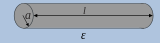


Here, if necessary, A denotes the area of the electrodes, d their distance, l their length,  as well as
  their radii and ε
  the permittivity (dielectric conductivity) of the dielectric. It is ε
  , where ε
  is the electric field constant and ε
  is the relative permittivity. In the schematic diagram, the conductors are colored light gray and dark gray, respectively, and the dielectric is colored blue.
Capacity calculations
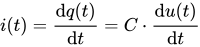
The following general equations for the determination of the capacitance apply to the respective time-dependent quantities current  , voltage
  and charge
  at a constant electrical capacitance :
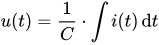
An expression for the capacitance of any electrode array or charge distribution can be derived using Gauss's theorem:
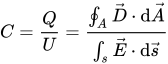
Here, the dielectric shift 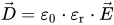 , thus:
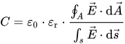
For a vacuum, this equation simplifies to because of ε 
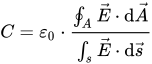
A calculation of the capacitance requires knowledge of the electric field. For this purpose, the Laplace equation  with a constant potential φ
  on the conductor surfaces must be solved. In more complicated cases, no closed form of the solution exists.

Measure capacity
The measurement of capacitance is not only used to control the capacitance of a capacitor (component), but is also used, for example, in capacitive distance sensors to determine the distance. Other sensors (pressure, humidity, gases) are also often based on a capacitance measurement.
According to the above relationships, the capacity can be determined as follows:
- Charging with constant current and observing the rate of voltage rise
- Measuring the resonant frequency of an LC resonant circuit formed with the capacitance.
- Applying an AC voltage and measuring the current waveform
In particular, the latter method is used in capacitance measuring devices, where not only the magnitude of the current but also its phase relation to the voltage is recorded. In this way, the impedance and the loss angle or quality factor of the capacitor can also be determined.
Related articles
Author
AlegsaOnline.com Capacitance: definition, principles, history, and practical uses Leandro Alegsa
URL: https://en.alegsaonline.com/art/16688