Blast furnace: large industrial furnace for smelting iron ore
A blast furnace is a tall industrial furnace used to smelt iron from ore into pig iron. This article explains its design, chemistry, historical development, uses, and environmental issues.
Overview
A blast furnace is a specialized furnace designed for the continuous smelting of iron from its ores. It is the principal reactor used in primary ironmaking and remains central to large-scale steel production. The blast furnace converts raw materials—iron ore, a carbon source, and flux—into molten iron and slag by applying heat and a directed stream of air called the blast.
Image gallery
10 Images


Structure and principal parts
Blast furnaces are massive vertical shafts often lined with heat-resistant materials. Typical elements include the outer shell, the internal refractory lining, the charging system at the top, the bosh and hearth at the bottom, and tuyeres where the hot blast is introduced. The outer shell is commonly a steel structure, while the internal walls are built from refractory bricks made from materials such as magnesium oxide or other refractory compounds to withstand extreme temperatures. Water cooling circuits are integrated into parts of the casing to protect the furnace from overheating and wear, with circulating water removing heat.
How it works: process and chemistry
The basic process is smelting: oxygen is removed from the iron-bearing minerals in iron ore, which is mostly iron oxides, producing metallic iron. A carbon source—normally coke derived from coal—serves both as fuel and as a reducing agent. At high temperatures the carbon and oxygen react to form carbon monoxide and dioxide; carbon monoxide then reduces iron oxides to metallic iron in a series of reduction reactions. The overall removal of oxygen from ore is called smelting or reduction, and it depends on sustained high temperatures and controlled gas flow. Fluxing agents such as limestone combine with impurities to form slag, which floats on the molten iron and is tapped off separately.
Operation, inputs and outputs
Charged from the top, the burden of ore, coke and flux descends as the hot blast—forced air preheated in stoves—enters near the bottom. This establishes temperature and chemical gradients within the shaft that drive the sequential reduction steps. The main product is molten pig iron, which can be cast or transferred to steelmaking furnaces; by-products include slag and off-gases that are often cleaned and reused for energy.
Scale, history and development
Blast furnaces are among the largest chemical reactors in continuous operation and may reach tens of metres in height and several metres in diameter; historically they have grown in size to improve efficiency and output, with some modern furnaces approaching the dimensions noted in industrial descriptions (size references). The technology evolved from small charcoal hearths to coke-fired industrial furnaces during the Industrial Revolution and has continued to be refined with better refractory design, automated charging, and gas recycling.
Uses, variations and environmental considerations
The primary purpose is to produce pig iron for steelmaking; variants and alternatives include direct reduced iron and electric-arc furnace routes that reduce reliance on coke. Environmental concerns focus on carbon dioxide and particulate emissions, energy consumption, and slag management. Modern plants employ gas cleaning, heat recovery, and process changes aimed at reducing greenhouse gases and improving material efficiency.
Key facts and further reading
- Definition and general info: furnace basics.
- Smelting and reduction processes: smelting, reduction.
- Raw materials: iron ore, ore sources, carbon.
- Chemistry: iron oxides and removal of oxygen.
- Design and materials: steel shell, refractory bricks including magnesia and other refractories.
- Cooling and utilities: water cooling, process engineering.
- Operational scale and dimensions: size considerations.
- Temperature and reduction agents: high temperatures, carbon.


History
For the earliest use and archaeological finds of iron, see.
→ Main article: History of iron use
The beginnings of iron smelting in Europe
A first simple and long used form for iron smelting were the so-called Rennfeuer (also called Luppenfeuer). A funnel-shaped pit about 30 centimetres in diameter was filled with charcoal and easily reducible grass iron ore, ignited and supplied with atmospheric oxygen by means of a hemispherical and fur-covered bowl (as an early form of bellows) acting as a fan. After about ten hours, a black slurry (iron sponge) about the size of a fist, interspersed with iron grains and unaltered ore and slag, had accumulated at the bottom. During the furnace journey, the iron does not liquefy in a racing furnace. Although it is possible to reach the temperatures required for this without any problems, the product obtained in this way would be heavily carburized and no longer forgeable. During operation, therefore, the temperature had to be kept constantly within a range that did not allow the metal to liquefy. The racing furnace, usually built of clay or stones, was a further development of the racing fire with a side opening for the air supply and a short shaft for charging and refilling charcoal before and during the furnace cycle. The shaft also supported the natural chimney effect, so that temperatures between 1000 and 1200 °C could be reached. The air supply was initially realized with a natural draught, for example by building on an embankment, and the furnaces were accordingly called wind furnaces or draught furnaces. In the blast furnaces, on the other hand, bellows provided a more effective and controlled air supply. Depending on the duration of the furnace cycle (4 to 20 hours) and the size of the furnace, the early smelters received a hull weighing from a few kilograms to several hundredweight. This was then freed from coal and slag by repeated heating (heating up) and forging, compacted and further processed - mostly via semi-finished products - into the desired workpieces.
See also: Iron production in the Lahn-Dill area and iron smelting among the Germanic tribes.
Until the 18th century, racing furnaces with attached forges, so-called racing mills, were still widespread. They employed about five to ten men and produced about 60 to 120 tons of slag annually. For every kilogram of iron, 2.7 kilograms of charcoal were burned.
Development of the blast furnace
Even though the racing furnace was used for a long time due to its simple design, more efficient furnaces began to be developed as early as the beginning of the 13th century. A link to the development of today's blast furnaces can be seen in the lump furnace (also known as the "wolf furnace"), which was named after the piece of iron that was taken out of the furnace. The furnace was a square-walled shaft furnace open at the top, the size of which grew from about four metres high in the late Middle Ages to ten metres high in the 17th century, such as the lump furnaces in Vordernberg in Styria, a centre of pig iron production in Central Europe at the time. The bellows of the furnaces were driven by waterwheels and the plants were therefore also called wheel works. They reached temperatures of up to 1600 °C; the mixture of iron ore and charcoal was partially melted in the process. A further development was the blue furnace, whose name was derived from a corruption of the English word blow. In principle, it corresponds to the lump furnace, but has a closed furnace breast.
However, at first only the iron sponge (Luppen) accumulated above the iron bath was processed further in the forges, reaching such a size in the lump furnaces that it was no longer worked on by hand, but with forging hammers also driven by water power. The molten pig iron resulting from the smelting process initially appeared to the smelters as "spoiled iron" that could not be used because it had absorbed such a high proportion of carbon that it was too brittle for forging. It was called Saueisen in Germany and Graglach, Dreckfluss in Styria and pig-iron in English-speaking countries.
It was not until the invention of various processes for refining iron, around the 14th century, that the problem was solved. This also paved the way for further increasing the efficiency of the furnaces. Raft furnaces with metre-thick masonry were built, whose frames were narrowed and where the pig iron (river iron and river steel) and the slag produced after completion of the smelting process were drained off together. Raft furnaces can be regarded as the direct "ancestors" of the blast furnace, since nothing changed in principle in the iron extraction process after their development. The oldest known raft furnace is in the Kerspetal (Bergisches Land). It is dated to the year 1275. Around 1450 there were around 30 blast furnaces in the Siegerland region. With the increasing efficiency of the furnaces and the rising demand for iron goods, however, a new problem arose: the demand for charcoal necessary for energy production could no longer be met. Hard coal was also used on an experimental basis, but could almost only be obtained by digging coal in opencast mines. In 1755 there were almost 200 collieries in the Ruhr area.
The Englishman Abraham Darby I (1676-1717) finally succeeded in producing pig iron using coke in Coalbrookdale in 1709, after several unsuccessful attempts with hard coal. Together with the steam engine improved by James Watt to drive the blowers, the efficiency of the blast furnaces was considerably increased. In Germany, on the other hand, similar attempts were initially unsuccessful. It was not until November 1796 that the Royal Steelworks in Gliwice succeeded in building a functioning blast furnace powered by coke. With the help of coke, the quantity of pig iron produced could be increased to two tonnes a day, with a consumption of three and a half tonnes of coke per tonne of pig iron. These quantities of pig iron could only be partially processed by the still small refining furnaces; the rest was used as cast iron.
With the development of cupola furnaces towards the end of the 18th century, the cast iron industry experienced a real heyday. Cannons, church bells, cookware and finally also objects of art such as stove and fireplace panels decorated with reliefs and even jewellery were made of cast iron. Among the largest cast iron products are the Iron Bridge in England, built in 1777/79, and the bridge built in 1794 over the Striegauer Wasser near Laasan (today Łażany) in present-day Poland, with a span of 12 metres.
A final significant improvement in blast furnace performance was the use of hot air, supplied first by tubular hot blast stoves (Neilson, 1828) and later by the Cowper hot blast stoves (1857) still in use today.
The earliest documented blast furnaces in Europe were in Sweden in the 13th century, for example in Lapphyttan. For the following centuries, there is evidence of individual blast furnaces in France, Belgium and above all England. The oldest, largely completely preserved blast furnace in Germany is the Luisenhütte in Wocklum near Balve in the Sauerland. In Saxony, three charcoal blast furnaces from the 17th and 19th centuries have been preserved in Brausenstein (1693), Schmalzgrube (1819) and Morgenröthe (1822). A blast furnace dating from 1783 can be seen at the Wilhelmshütte in Bornum am Harz, and in the Sauerland region the Wendener Hütte, also built in the 18th century, has been declared a technical cultural monument. In Thuringia, the blast furnace museum Neue Hütte (Schmalkalden) is located in Schmalkalden-Weidebrunn. The late classicist blast furnace plant from 1835 shows how pig iron was produced from local iron ores on a charcoal basis. The smelter existed until 1924.
Iron smelting outside Europe
The tatara furnace, a special type of racing furnace used in Japan to produce iron, has been known since at least the 7th century. Unlike the furnaces used in other regions of the world, a Tatara furnace is box-like in shape with a height of about 1.2 to 2 meters with an upper width of 0.8 to 1.2 meters, tapering to only about 0.5 meters at the bottom. The length of the oven, on the other hand, is about 4.5 metres. On both long sides, 18 to 20 ceramic nozzles provide a sufficient air supply, which in "modern" kilns is brought in by a fan driven by several men. The Tatara kiln is fed alternately with charcoal and iron ore sand, and reaches temperatures of 1200 to 1500 °C. The kiln walls are then heated for about three days. After about three days, the furnace walls are smashed and a block of forgeable iron and steel weighing about two tons is removed. The resulting slag was previously drained off during operation. Even today, the Japanese steel (tamahagane) traditionally produced in Tatara furnaces and known for its quality is used, for example, for high-quality kitchen knives (Hōchō) or for the Japanese long sword katana.
Chinese iron smelting furnaces of the 19th century resembled an upside-down truncated cone about 2.5 metres high with an upper diameter of 1.2 metres, a lower one of just under 60 centimetres and a wall thickness of 30 centimetres and were built of clay. To secure it, the furnace was surrounded by a basket of iron mesh and could be tilted about 30° to facilitate removal of the pig iron. The furnace was fed with brown ironstone, blackband ironstone and, depending on the type of construction, charcoal or coke. The air required to reduce the ore was introduced by a manually operated cylinder blower. In this way, between 450 and 650 kilograms of pig iron could be produced per day with a coke consumption of 100 kilograms per 100 kilograms of iron. A similar blast furnace plant was also found in the province of Bulacan in the Philippines, which operated until around 1900. The blast furnace was in the form of an upside-down truncated cone, closed at the bottom, with an external height of 2.1 metres, an external diameter at the gout of 1.5 metres and a wall thickness of between 30 and 80 centimetres.
In Africa, peoples were discovered as late as the beginning of the 20th century who reduced iron ore with the help of one to three meter high shaft or train furnaces. For the construction, either termite mounds were used, which were suitably hollowed out, or the furnace was built from clay. Several ceramic nozzles inserted at the bottom of the furnace provided sufficient air supply, which was sucked up through the ore and coal charge due to the chimney effect of the high shaft. Ore and coal were replenished several times through the upper chimney opening until, after about 20 hours, a football-sized louvre was produced, which was removed at the bottom through the broken open furnace breast. The very pure iron ore required for these furnaces came from Banjéli in Bassariland, among other places.


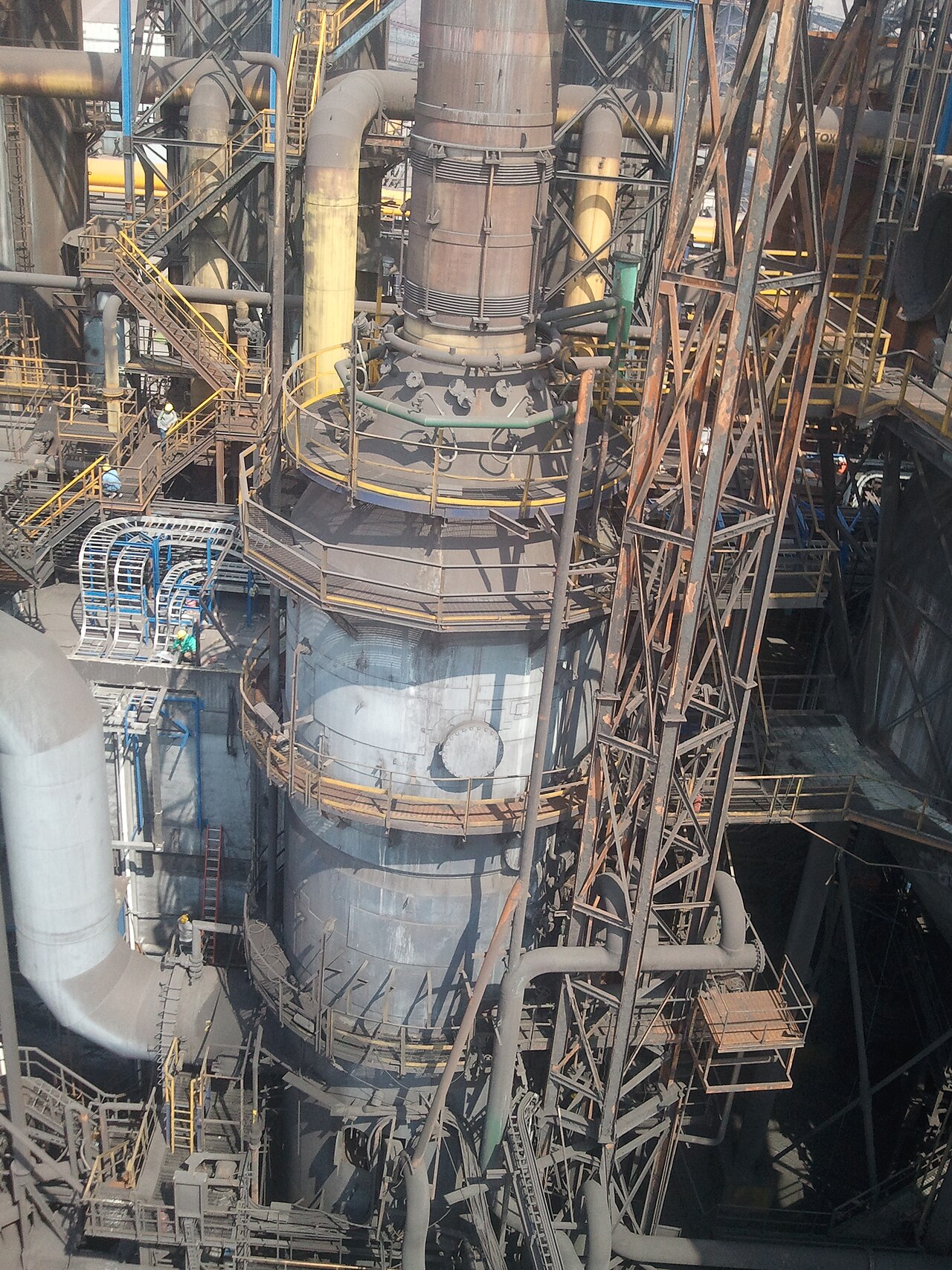
Structure
In order to ensure smooth continuous operation during the so-called "furnace journey" of 10 to 20 years until the next due maintenance date, a blast furnace plant requires further essential equipment in addition to the blast furnace itself. These include the bunker for the charge materials with a connected transport system for continuous charging of the blast furnace, with which the charge materials are fed into the blast furnace via the blast furnace top. The air preheated in the hot blast stove is blown through nozzles into the blast furnace via a hot blast ring line. The blast furnace is lined with refractory on the inside and surrounded by a complex cooling system on the outside. Connected to the blast furnace is a specially designed tapping or casting hall in which the pig iron extracted during the regular tapping operations can be fed into appropriate ladle or torpedo wagons and transported away for further processing.
The construction of a modern blast furnace plant is an extensive major project of an iron and steel works and takes between 1.5 and 2.5 years from planning to commissioning, of which the planning work takes about half the time. The investment costs for the construction of the new "Blast Furnace 8" in Duisburg-Hamborn, for example, amounted to around € 250 million.
Bunker
The feedstocks, such as iron ore, coke and aggregates (e.g. lime, sand and dolomite), which are usually delivered by rail or ship, are first taken to a bunker plant. This consists of several bunkers, either bricked or cast from reinforced concrete, in which the incoming raw materials are stored. In order to compensate for the quality differences in the composition of the burden (iron ore, aggregates) and coke, the materials are often mixed beforehand on so-called blending beds.
Some raw materials are already prepared by the suppliers (including mines). In some cases, upstream preparation, for example in an ore crushing, sintering and pelletizing plant, must ensure processing, as the particle or grain size of the raw materials must be neither too small (risk of clogging, poor through-gasification) nor too large (no optimum raw material utilization).
Feeding
From the bunker, burden and coke are transported to the top of the shaft, the so-called gout. The feeding of the material is also referred to as charging or charging and, depending on the space available, is carried out either by belt conveyors, skip hoppers or small hopper wagons, so-called lorries or hoppers (also dogs).
In the case of car charging or "skip charging", charging takes place via an inclined elevator up to the charging opening known as the "blast furnace sluice", which forms the top closure of the blast furnace. Two elevator systems are used for each blast furnace, alternately transporting coke and burden. In addition to the greater supply capacity, the use of two elevators also serves as a safety measure against breakdowns in order to ensure the uninterrupted supply of the blast furnace. Conveyor belts are now the preferred method of charging in modern blast furnaces. Although these can only overcome small gradients and require more space, they are more efficient, can be automated more easily and handle the bulk material more gently.
Gauge shutter
The blast furnace gas escaping from the furnace head consists largely of hot nitrogen (N2), carbon monoxide (CO) and carbon dioxide (CO2) as well as small amounts of other gases and entrained dust (see also under blast furnace products). Despite the hazardous nature of this toxic and flammable gas mixture, the blast furnace opening remained unsealed for a long time. It was not until the development of blast furnace gas-fired hot blast stoves in the 19th century that these were fitted with a sluice system, which made it possible to feed the blast furnace without losing the now valuable fuel and heating gas. The blast furnace gas is collected via large pipes, freed from the dust it carries and then fed to the burners of the hot blast stoves, among other things.
The first hopper closure with a simple hopper sluice was invented by George Parry in Ebbw Vale in 1850, and later became known as the "Parry hopper". However, the most widespread form of hopper gate until the 1970s was the "double bell gate" with an intermediate rotary hopper developed by McKee to distribute the bulk material. However, systems with three or four bells were also used to reduce the dump height, which could compromise the defined diameter of the ore pellets, and in blast furnaces with higher gout back pressure. The great weight of this design and the increasing problems in maintaining the tightness of the bell system finally put a limit to the efforts of increasing the performance of blast furnaces with bell closure.
A significant improvement of the blast furnace top was first brought about by the invention of the Luxembourg company Paul Wurth S. A., namely Édouard Legille, who developed the so-called "bell-less blast furnace top" (later also "Paul Wurth blast furnace top") in 1970/1971. Instead of a complex and heavy bell system, there are now two or more storage bins for coke and burden on the furnace head, depending on the size and requirements of the blast furnace, which are filled with charging cars via belt distributors or elevator systems. Coke and burden are conveyed through downcomers to the center of the furnace shutter to a rotating and pivoting chute that can distribute the incoming material precisely and evenly over the charging surface. The system is sealed by sealing flaps located above and below the storage bins. An additional material flap under the bins ensures a constant discharge speed of the bulk material. The overall height of the new "bell-less charging gate" was reduced by about 1/3, which also reduced the weight of the construction accordingly, and the tightness of the system was easier to guarantee.
On January 9, 1972 the world's first bell-less blast furnace top was put into operation at blast furnace 4 of the August Thyssen ironworks in Hamborn. Due to its many advantages over the old system, the bell-less Paul Wurth blast-furnace top has successfully established itself and is the preferred choice for modern blast-furnace plants.
Blast Furnace
Design
As a shaft furnace, the blast furnace itself is similar in principle to a chimney or stack, as this shape facilitates optimum gas flow through the charge due to the resulting stack effect. The height of the blast furnace core determines its efficiency and can be between 30 and 75 m. The upper 3/5 of the blast furnace core form the actual blast furnace. The upper 3/5 form the actual shaft, which corresponds to an elongated truncated cone. Connected to this is a short cylindrical intermediate ring with the largest internal diameter on the blast furnace, known as the "coal sack". Another upside-down truncated cone, the so-called "Rast", finally leads into the lower, cylindrical "Gestell". The coal sack, the rest and the frame each make up 1/5 of the total height. With a total height of 30 m, the shaft is about 18 m high, the coal sack and rest about 6 m high and the frame also 6 m high.
The entire blast furnace structure is typically surrounded by a steel frame with working and assembly platforms, which on the one hand serves to accommodate the auxiliary equipment such as the material hoist and, if necessary, the blast furnace sluice, but which can also be used to support and stabilize the blast furnace. A distinction can be made between two types of support structure:
Older and predominantly American blast furnaces are fitted with a support ring with support columns at about the level of the rest, via which the load on the blast furnace is transferred from the furnace head and blast furnace sluice into the foundation. The support columns, however, cause a narrowing and thus obstruction of the access to the tapping area as well as problems in the connection area between the rest and the support ring. Due to these disadvantages, the second variant is now preferred in newer blast furnaces.
This design, developed in Germany, is a so-called "free-standing blast furnace". The steel armouring of the blast furnace results in a self-supporting furnace construction, which is surrounded by a complete scaffolding for working platforms and to accommodate the auxiliary equipment. This eliminates the disturbing columns in the tapping area and the blast furnace can freely follow all thermal expansions, which are absorbed by a compensator attached to the furnace head.
The total height of such a plant is about 90 m. Blast furnace 2 in Duisburg-Schwelgern, for example, has a furnace height of almost 75 m, a hearth diameter of 14.9 m and a useful volume of around 4800 m³, melts around 12,000 t of pig iron every day and is currently (as of 2014) considered the largest blast furnace in Europe. Twelve blast furnaces in the world exceed 5,500 m³ usable volume (as of 2013). The largest known blast furnace in the world to date, with a useful volume of 6,000 m³, is located at POSCO's "Gwangyang Steel Works" in the South Korean province of Jeollanam-do.
The tapping opening for the pig iron, which is closed with a ceramic plug, is located at the lower end of the rest and can be used to drain off the pig iron and slag produced by the smelting process. For complete emptying ("sow tapping") in the event of a forthcoming relining of the blast furnace, a "sow hole" (also furnace sow) is provided at the lowest point of the rack and in its base.
The nozzles of the hot blast ring line start at the boundary between the rest and the rack and are supplied by blast heaters.
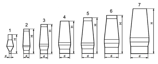
| Development of profile and size in the course of history (lengths partly rounded) | ||||||
|
| Region and period | Frame Ød | HeightH | net content in | Output in tons |
|
| 1) Blast furnace 1861 | 0,9 | 15,3 | 64 | 25 |
| |
| 2) West German special pig iron blast furnaces of the 1930s | 4,5 | 20,0 | 425 | 450 |
| |
| 3) West German steel and Thomas pig iron blast furnaces 1961 | 6,5 | 24,0 | 900 | 1.200 |
| |
| 4) West German blast furnaces 1959 | 9,0 | 26,1 | 1.424 | > 2.000 |
| |
| 5) Soviet blast furnaces 1960 | 9,8 | 29,4 | 1.763 | 4.000 |
| |
| 6) Japanese blast furnaces 1968 | 11,2 | 31,5 | 2.255 | 6.000 |
| |
| 7) West German large blast furnaces 1971/72 | 14,0 | 36,7 | 4.100 | ≈ 10.000 |
| |
Bricklaying
Originally, blast furnaces consisted of a load-bearing and heat-insulating masonry wall of bricks or rubble stones several meters thick on the outside (smoke wall) and a refractory lining on the inside (core wall). In modern blast furnaces, centimetre-thick steel armouring and supporting scaffolding bear the load, while the core masonry alone provides the necessary fire resistance and thermal insulation.
In order to achieve the desired service life (furnace travel) until the blast furnace lining is due for complete replacement, the entire blast furnace core is lined with refractory from the shaft to the hearth. The furnace lining also determines the final internal profile of the furnace. With a total area of around 2,000 m² and a thickness of a few decimetres to over a metre, oversized linings can incur enormous costs, which is why every effort is made during the planning stage to use only bricks that are specifically matched to the requirements of the particular furnace section.
In the upper shaft area, the temperatures are relatively low, while the mechanical stresses are high due to the impacting charge. Accordingly, fireclay with a corundum content of between 30 and 40 % is used here. In addition, "impact armour" made of steel plates is installed in the inlet area of the charge to prevent damage to the brick lining by the impact of the charge materials.
In the lower shaft area up to the coal bag, the temperatures increase rapidly. However, the stress due to abrasion decreases only slowly, since the charge should remain solid for as long as possible and withstand the pressure of the burden column in order to allow good through-gasification. In addition, the bricks in this area must be chemically stable, as the reactivity of the surrounding materials increases. Accordingly, highly refractory fireclay with a corundum content of between 60 and 86 % or semi-graphite bricks are used here.
At the height of the wind nozzles and in the rest area, the lining is exposed to the highest temperatures and pressures, which are only withstood by carbon bricks, fused spinel bricks with chrome oxide or chrome corundum bricks.
Cooling
To protect against overheating, the blast furnace contains a system of cooling water pipes and elements (staves) connected to the armouring from about the upper third of the shaft down to the bottom of the hearth. Since a blast furnace with a hearth diameter of 8 m has a water turnover of more than 30,000 m³ per day, which corresponds approximately to the consumption of a medium-sized city with about 200,000 inhabitants, the cooling system must be designed accordingly and secured several times to protect against failure.
In modern blast furnaces of the 20th century, the open cooling circuits that were widespread in the past are mostly only used for furnace head and rack sprinkling and in emergencies (e.g. in the event of failure of a closed circuit). In open circuits, the required water is taken from nearby bodies of water (rivers, lakes) and cleaned of solids before being used in the cooling system. After use, cooling towers recool the water before it is returned to the environment. Closed-loop systems, on the other hand, use treated, desalinated and degassed water that is cooled down again after use via heat exchangers and then fed back into the cooling system. In addition to protecting the cooling elements and pipes from deposits, treated water has the advantage that the cooling system can absorb larger amounts of heat.
The design of the cooling elements is such that, on the one hand, they can support the brick lining, but on the other hand they can also be replaced quickly if damaged. They are made either of sheet steel, cast iron or copper and are either bolted, wedged or welded to the lining. Two basic designs can be distinguished in the design of the cooling elements:
- Cooling boxes are flat, rectangular elements with labyrinthine baffles to direct the flow of water and a profile that tapers towards the centre of the kiln, allowing rapid removal and installation. The cooling boxes are inserted between the armour plates of the shaft, creating a checkerboard pattern of armour plates and cooling boxes.
- Plate coolers or staves are made of special cast iron with cast-in vertical cooling tubes. They are bolted to the side of the armour facing away from the centre of the furnace. The bearing surface of the staves is criss-crossed with grooves which are filled with insulating compound.
Different types of cooling are used at the blast furnace depending on the cooling capacity requirements. The furnace head is cooled in the area of the impact tanks with an external sprinkler system. Cooling boxes are mainly installed in the shaft area and cooling boxes and plate coolers are used in the coal bag and rest area. Due to the particularly high heat load in this area, the cooling elements are closely spaced so that as much heat as possible can be dissipated. The blow moulds are provided with their own double cooling circuit. The frame and base are cooled either with trickling water or by introducing water into a double frame jacket.
Winderhitzer
James Beaumont Neilson was one of the first to develop and patent recuperative hot blast stoves - the air required is heated by heat exchangers. Previously, blast furnaces had always been operated with cold air, as it had been the experience of metallurgy since time immemorial that a blast furnace ran better in winter than in summer. For this reason, Neilsen initially met with great resistance in his attempt to use the new principle. Even a trial permitted by the Clyde Iron Works in 1828 using a blast of wind heated to only 27 °C, which nevertheless ensured that the slag produced was lower in iron and considerably more fluid, did not yet convince the workers. Neilson's rather simply constructed hot blast stoves consisted of a piece of feed pipe bent into the shape of a vault, which was heated over a grate fire. A sheet metal box mounted above the pipe vault held the heat for a while to improve heat transfer. Further design improvements through the use of more heat-resistant cast iron tubes and boxes, as well as extended and bent heating coils to absorb the thermal expansion, enabled these "tubular blast stoves" to heat the blast wind up to 315 °C.
| Comparison of pig iron quantities achieved using different fuels and blowing in cold and hot air | |||
| Year | Wind system | Fuel consumptionin | Quantity of pig iron in |
| 1829 | Cold Wind | Coke 8060 | 1607 |
| 1830 | Hotwind | Coke 5160 | 2353 |
| 1833 | Hotwind | Raw coal 2280 | 3556 |
Resistance to the use of hot blast ceased altogether when the pig iron yields achieved increased ever more markedly and at the same time the quantities of fuel required could be considerably reduced. Even raw coal could now be used, which had previously been impossible.
Since the middle of the 18th century, there is evidence that blast furnace gas has also been used in metallurgy, but initially only for roasting ore, drying casting moulds and burning lime and bricks. It was not until the beginning of 1832 that Wilhelm von Faber du Faur succeeded in developing an effective and stable tubular blast furnace, the "Wasseralfinger Winderhitzer", which was heated with blast furnace gas and raised the wind temperature to 540 °C. This, however, was also the limit of the performance of this blast furnace. However, this also reached the performance limit of this design.
Finally, Edward Alfred Cowper (1819-1893) achieved a decisive improvement in the supply of hot air to the blast furnaces by designing the hot blast stoves with refractory, air-permeable multi-hole bricks instead of a system of tubes. Already in the first stage of development, the "Cowper wind heaters" brought 29 m³ of air to a temperature of 650 to 700 °C within one minute. At that time, the wind temperature could only be measured with melting samples of various metals. The previously used samples of lead (SP = 327.4 °C) and zinc (SP = 419.5 °C) could no longer be used with Cowper's wind heaters and even antimony (SP = 630.6 °C) melted within seconds. Another innovation, also developed by Cowper, was the regenerative alternating operation of two hot blast stoves, in which one was heated by blast furnace gas firing while the other released the stored heat to the blown-in cold air.
More modern "Cowper wind heaters" consist of a vertical steel tube 20 to 35 m high with a diameter of 6 to 9 m. The inner wall is made of a layer of heat-insulating bricks and then a layer of refractory bricks. To the inside, there is first a layer of heat-insulating bricks and then a layer of refractory fireclay bricks. The core consists entirely of superimposed multi-hole bricks made of silica. On one side of the shaft, a combustion shaft, also lined with refractory, is divided off up to the height of the dome, which takes up about one third of the cross-section of the hot blast stove. The combustion nozzles and the connections for cold air and hot air are located at the lower combustion shaft. Another possibility is the construction of an external combustion shaft independent of the hot blast stove shaft. This design has the advantage that, on the one hand, cracks that occur due to the strong temperature fluctuations in the partition wall between the combustion and heating shafts are avoided and, on the other hand, the hot blast stove itself has more space for multi-hole bricks and thus the heating capacity can be increased once again.
Usually three, or in the case of larger blast furnaces four "cowpers" ensure a smooth and trouble-free supply of hot air to the blast furnace. While two are heated up with a time lag, an axial or radial blower forces cold air (around 1.4 t per ton of pig iron) through the third cowper at a pressure of 2 to 4.5 bar. The steam or gas piston blowers previously used proved to be uneconomical and difficult to control. In the continuous cycle, a changeover is then made to the previously longer heated cowper, while the cooled cowper is heated up again. The heating phase lasts about 50 minutes, while the wind phase lasts only about 30 minutes, since the wind heater must not fall below a temperature of 721 °C, which is critical for silica bricks. Silica bricks undergo several modification changes below this temperature, which leads to a "volume jump" that destroys the solid structure of the multi-hole brick set and can cause it to collapse. The third or fourth "cowper" also serves as a reserve against failures and during maintenance work.
Hot blast ring line and nozzles
With a maximum achievable temperature of 1270 °C (1980) to 1350 °C (1985), the hot blast passes via the "hot blast ring line" to between 10 and over 40 nozzles, depending on the size of the blast furnace, and via the so-called blow moulds into the furnace. To reduce coke consumption, in many plants substitute reducing agents are injected via the moulds, such as animal fat or heavy fuel oil. However, as the price of oil continued to rise over time, various attempts were made to use other substitutes.
At Armco in the USA, pulverized coal was successfully used as a fuel substitute over longer periods and in Chinese plants even in continuous operation from 1963 onwards. Since 2006, finely pelletized waste plastics (6 mm × 9 mm) have also been added, which, in addition to the environmentally friendly recycling of plastic waste in contrast to landfilling, also reduces the emission of CO2 and SO2.
To protect against damage caused by the heat load, the ring pipe and the feed spigot are given a refractory lining which at the same time has a heat-insulating effect in order to prevent heat loss. The blow molds themselves are cooled intensively with water, as they can protrude up to half a meter into the furnace depending on the degree of wear of the blast furnace lining and are then exposed to the highest stresses due to the temperature and pressure of the burden column. In modern blast furnaces, therefore, only hollow shapes made of electrolytic copper with a double-chamber cooling water circuit are used. If the front chamber burns down in the course of the furnace journey, the corresponding cooling circuit can be switched off and continued with the main chamber until the next standstill.
Pig iron and slag tapping
Hot metal tapping takes place at regular intervals of about two to three hours. The ceramic plug at the tapping opening is drilled out with a compressed air drill. In rare cases, for example if the drill should fail, the opening is also pierced with an oxygen lance.
The pig iron then flows for about 15 to 20 minutes in a specially designed tapping or casting hall with a working platform and a refractory brick channel system, which is additionally lined or poured with refractory mixes. In older blast furnaces with higher slag production, part of the slag was first tapped off as so-called "preliminary slag" at the level of the mould platform. Then the pig iron and slag were tapped further together via a kind of siphon, the so-called "fox", which separated the slag from the pig iron (in the manner of decanting) and diverted it in different directions via an appropriately designed channel system. Modern blast furnaces with lower slag production but a daily pig iron output of 3,000 tonnes and more no longer need a preliminary tapping of the slag, but instead between two and four tapholes. The system of troughs and chutes is correspondingly complex and requires careful monitoring.
In the main channel between the taphole and the fox, which is about 8 to 14 metres long and holds about 20 to 60 tonnes of pig iron together with slag, the slag has time to separate from the pig iron and collect on the surface. In front of the fox, whose "nose" dips into the molten metal, the slag accumulates and is discharged via laterally branching channels. The pig iron, on the other hand, flows under the fox to a hole under which a ladle or torpedo car is waiting to transport the collected iron to the steelworks or foundry for further processing. The slag is also collected in special wagons and transported away for further processing.
After completion of the tapping phase, the taphole is closed again with the aid of a "taphole plugging machine" until the next tapping.
Modern casting halls must be "dedusted" to protect employees and the environment, which means that extraction systems are installed in the area of the tap holes and at the transfer point to the collecting tanks, and the channel system is covered with steel plates. The collected exhaust gases are cleaned in appropriate filter systems.


Questions and answers
Q: What is a blast furnace?
A: A blast furnace is a large furnace used for smelting iron from ore.
Q: How big can blast furnaces be?
A: Blast furnaces can be up to 60 metres tall and 15 metres in diameter.
Q: What is another name for a blast furnace?
A: Blast furnaces are also called high ovens.
Q: What materials are blast furnaces made of?
A: Blast furnaces are usually built with a steel case and bricks made of magnesium oxide or other refractory materials.
Q: How is the blast furnace cooled?
A: The blast furnace is cooled with water running inside part of the case and bricks.
Q: What is the process of smelting and how is iron made?
A: The process of making iron is smelting, which involves removing the oxygen from iron ore. Carbon is used in the reduction process, with the ore heated to a high temperature. This leaves crude iron called pig iron.
Q: What is carbon's role in the reduction process for making iron?
A: Carbon easily takes the oxygen off the ore in high temperatures.
Tags
Related articles
Author
AlegsaOnline.com Blast furnace: large industrial furnace for smelting iron ore Leandro Alegsa
URL: https://en.alegsaonline.com/art/12114