Bernoulli's principle
Bernoulli's equation, also known as Bernoulli's law or (ambiguously) Bernoulli's theorem, is a statement about flows according to Bernoulli and Venturi. The theory about these essentially one-dimensional flows along a stream was laid out in the 18th century by Daniel Bernoulli and Giovanni Battista Venturi and is the basis for important aero- and hydrodynamic calculations.
Bernoulli's equation states for the steady-state flow of viscosity-free incompressible fluids (liquids and gases) that the specific energy of the fluid elements is constant along a streamline:
Here u is the velocity, p the operating pressure, ρ the density, g the gravitational acceleration and z the height above a reference plane in the earth's gravitational field. The operating pressure is that part of the static pressure that does not result from the fluid's own weight. The first summand represents the specific kinetic energy, the second the specific pressure energy and the third the specific position energy. The total specific energy e, which is constant on the streamline, is determined by suitable reference values on the streamline and represents an integral of the movement along the streamline.
Multiplying the equation by the (constant) density ρ yields the Bernoullian pressure equation
where the total pressure 


In it, the sum of the velocity height 


Instationarity of the flow, compressibility and viscosity of the fluid as well as rotation of the reference system can be taken into account by extending the Bernoulli equation. Thus, it finds a wide range of applications in the design of technical pipe flows, in turbomachinery and wind turbine construction as well as in measuring instruments (Pitot tube, Prandtl probe).
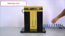
Play media file The observations on the Venturi tube explain Bernoulli's equation
History
Today, Bernoulli's equation can be derived from the Navier-Stokes equations or the law of conservation of energy for the fluid elements along a streamline. However, since these relationships were not found until the 19th century, Daniel Bernoulli could not use them in his derivation in 1738. Instead, he used the preliminary work of Evangelista Torricelli, Christiaan Huygens and Gottfried Wilhelm Leibniz.
Torricelli applied Galilean laws of falling to outflowing fluids in 1640, which led to Torricelli's law of outflow. Huygens realised in 1669 that the equations for elastic impact established by René Descartes are correct if one counts the velocities taking into account their sign. In 1678, Leibniz concluded from Huygens' law of elastic impact that the product of mass and the square of velocity, twice the kinetic energy, are identical before and after the impact.
Daniel Bernoulli published his Hydrodynamica in 1738, see pictures, where in Sectio 12 he combined the results of Torricelli and Huygens on a ball of fluid (abdc in his Fig. 72). He thus succeeded in determining the pressure of flowing fluids on walls and in revealing the role of the loss of kinetic energy, which he called vis viva, in sudden changes of the flow cross-section.
In 1797, the Italian physicist Giovanni Battista Venturi published his discovery that the flow velocity of a liquid flowing through a pipe is inversely proportional to a changing pipe cross-section. Venturi was also able to prove experimentally that the static pressure at the constrictions is lower than at the wider sections, see the illustration of the Bernoulli effect below.
Bernoulli and Venturi considered the quasi one-dimensional flow with plane cross-sections, which today is the subject of hydraulics and not hydrodynamics.
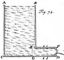
Bernoulli's Fig. 72 on its derivation

Title page of Bernoulli's "Hydrodynamica
Application areas and limitations
Strictly speaking, Bernoulli's equation only applies to points on the same streamline, which presupposes knowledge of the velocity field. In two technically significant cases, the restriction does not weigh heavily:
- On the one hand, along flow tubes with inlet and outlet connected by a "middle" current thread, which is thus fixed. This is the field of hydraulics. Also in the #example below, each fluid element must run from the surface to the outlet, a knowledge that is already sufficient to solve the problem.
- On the other hand, in rotation-free, laminar flows far away from the edges of the flow. Such flows can be regarded in good approximation as potential flows, in which the Bernoulli equation applies globally between any two points of the area, see the #application to the wing profile.
Bernoulli's equation can also be applied in a modified form to compressible barotropic fluids. The use is again permitted in two significant cases:
- if the density-pressure relation is of the form ρ(p,T) and the temperature field T is homogeneous, i.e. only isothermal changes of state occur, or
- if the density-pressure relation is of the form ρ(p,s) and the entropy field s is homogeneous, i.e. only isentropic changes of state take place.
On the other hand, if fluid elements along a streamline undergo, for example, a Carnot process, they perform work, release energy in the process and Bernoulli's equation loses its validity.
Properties of the flows according to Bernoulli and Venturi
Venturi effect
Giovanni Battista Venturi discovered the law of continuity for incompressible fluids: For a given volume flow A - v, the flow velocity v of an incompressible pipe flow is inversely proportional to the pipe cross-section A, so that the volume flow is constant over any cross-section, see figure. There Δx1,2 = v1,2 Δt and with the constant volume V = A1 Δx1 = A2 Δx2 follows:
This means that the velocity of the fluid is greatest where the cross-section of the pipe is smallest. This effect is colloquially called the nozzle effect. However, the above relationship only applies as long as density changes are insignificant, which is a good approximation for flow velocities far below the speed of sound, see the figure in the derivation below. In the case of supersonic flow in a nozzle, the effect is reversed: a decreasing cross-section leads to a decrease in velocity and vice versa, which is explained in the last two articles and exploited in the Laval nozzle.
The Venturi effect is noticeable in everyday life, for example, when wind between houses increases in strength.
Bernoulli effect and hydrodynamic paradox
Venturi was also able to prove experimentally what Bernoulli's equation predicted, namely that the static pressure decreases at the constrictions in the Venturi nozzle, see Fig. 11 in the figure. The force to accelerate the fluid particles into the constriction is the pressure gradient force and its work p - V (specific 
The fact that the pressure is lower at a location where the flow is faster is called the Bernoulli effect. This effect can be demonstrated in a simple experiment, see sketch: Air is blown (light blue) between two sheets of paper (grey) suspended over rods (brown). Due to the higher ambient pressure compared to the reduced pressure in the air stream, the sheets are pressed together (black).
This fact is the hydrodynamic paradox: instead of the blown-in airflow pushing the blades apart, they move together. Objects adjacent to flow zones of gases or liquids are drawn into them. Similarly, a hose expelling water and held vertically against a wall under water is not repelled by the wall but drawn towards it.
The human vocal folds are stimulated to vibrate by the Bernoulli effect, which leads to voice formation. The Bernoulli effect is technically exploited in jet pumps, in chimneys and in flying, see also the application below.
However, the Bernoulli effect can also have undesirable effects: if two ships are on a parallel course, the effect can deflect the ships in such a way that they collide. Similarly, if a ship is travelling fast and there is little water under its keel, it can run aground because the Bernoulli effect sucks it towards the bottom. The same principle of action can lead to respiratory distress in strong winds, when the wind sucks out the air resting in the airways as a result of the Bernoulli effect. Strong winds sweeping over houses also have a reduced pressure compared to the spaces under the roof tiles, resulting in a wind load that can cover house roofs.
Further conclusions from Bernoulli's equation
Bernoulli's equation explains the following facts in a steady, lossless and incompressible flow along a streamline:
- Pascal's law: At constant flow velocity - especially at rest - the pressure decreases with height (or increases with depth): Δ
.
- Torricell's outflow law: At constant external pressure, the square of velocity increases with decreasing altitude (or increasing depth): Δ
.
- Venturi effect: In horizontal flow, the velocity square decreases in the direction of a pressure increase: ρ
.
The delta Δ represents the difference at locations 1 and 2 on the streamline. Furthermore, when comparing the physical states at two locations on the streamline, the following applies:
- At the same speed and pressure, the height at the points must also be the same.
- At the same speed and the same altitude, the pressure difference at the points is zero.
- At the same pressure and the same altitude, the velocity at the points coincides.
Application
Bernoulli's principle can be applied to many things in everyday life. Here are some examples:
- An aerator at the spout of a water fitting draws in air ("bubbles").
- A fire brigade proportioner for producing extinguishing foam works in a very similar way.
- Perfume diffuser with rubber blowball.
- Airbrushes, compressed air spray guns for paint, oil and others.
- Airless paint spray gun and Weingarten backpack sprayer draw in air during atomisation to distribute the liquid particles like a mist.
- Pressure differences on an airfoil are described sufficiently well up to speeds of about 300 km/h, which is an indication that the flow behaves like a potential flow in which the Bernoulli equation applies globally, i.e. between any two points of the flow area. If - as can be seen from the graph - the smoke filaments are closer together along the upper side of the wing and thus the air flows faster than in other areas, then Bernoulli's equation implies that the static pressure is lower there than in the other areas. On the underside, where the smoke filaments are further apart and thus the air flows more slowly, there is a correspondingly higher static pressure. Bernoulli's equation uses the streamline diagram to explain the pressure differences on an airfoil; however, it does not explain why the flow is faster on the upper side than on the lower side. (The pressure differences are a consequence of the deflection of the flow; see also dynamic lift).
- Prandtl's pitot tube, which is used, among other things, to measure the speed of an aircraft. Due to the presupposed incompressibility, it only provides reliable results in subsonic flight (e.g. sports aircraft) with the same restriction.
- Water jet pump.
- Lip-blocking, a breathing technique for bronchial asthma and COPD.
- Intake funnel of a carburettor. The Venturi flow meter and the Venturi nozzle are also named after their inventor.
- Ventilation and de-aeration of ships by wind scoops and dorade fans.
- Ecological energy supply through vertical wind turbines in the Pearl River Tower (a high-rise building in Guangzhou).
For these applications applies:
- Since Bernoulli's law only applies along a streamline, freedom from vortices must be required in the area of the flow under consideration.
- Bernoulli's law does not establish causality, but a relation between velocity and pressure field.

Flow pattern of smoke filaments (grey) from left to right around an airfoil (black). Where the streamlines (smoke threads) are close together, the speed is high, elsewhere it is lower. (Graphic based on a video still)

Play media file Bernoulli effect in the water jet
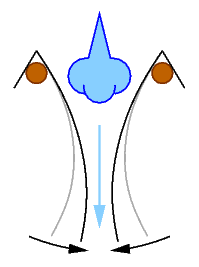
Experimental sketch of the Bernoulli effect: Air (light blue) blown between two sheets of paper (grey) causes the sheets to move together (black).

The fluid bales (grey) have the same volume.
.jpg)
Venturi's Fig. 11 shows the pressure drop at the constriction
Classical formulation for incompressible fluids
Energy equation
Bernoulli's equation consists of three terms and can be clearly explained using a piping system for a dam and the law of conservation of energy. The energy is given as a specific quantity, i.e. related to the mass of the fluid ( 
The first partial term is the velocity energy ek (kinetic energy) of the fluid, which results from the flow velocity u. The first partial term is the kinetic energy. If the pipe narrows, the flow velocity increases according to the law of continuity and thus the kinetic energy.
If the pipeline now runs over a height difference z, then the position energy ep comes into play via the gravitational acceleration g. The position energy of the flowing fluid is lower at the lower end of the dam. At the lower end of the dam, the position energy of the flowing fluid is lower.
In order for the energy to remain constant according to the law of conservation of energy, a third partial term, the pressure energy wp, is needed in addition to the position energy and the kinetic energy. It is the work required to push a particle from an area with lower pressure into an area with higher pressure, as is the case at the lower end of the dam. The smaller the density ρ of the particle (large volume) and the greater the pressure difference p, the more work the process requires. In the funnel-shaped constriction, the flow velocity increases due to the constant volume flow, which means that the fluid must be accelerated by a force. This force results from the pressure before the constriction and reflects the pressure energy that each unit of mass of the fluid flowing through the pipe carries with it. This results in the energy equation given at the beginning for incompressible media
Height equation
Division of the Bernoulli equation by the acceleration due to gravity shows: For the stationary (not changing in time) motion of an ideal (viscosity-free), incompressible fluid subject only to gravity, for all points on a streamline, the sum of velocity height 


The velocity height can be understood as the dynamic pressure of the flow, the pressure height as a measure of the pressure of the fluid. This sum h, which is constant along the streamline, is called the energy height and is given in metres.
Pressure equation
Multiplying the Bernoulli energy equation by the density ρ gives the Bernoulli pressure equation:
The total pressure pt is therefore the sum of
- the operating pressure p, which is that part of the static pressure that does not result from the fluid's own weight,
- the hydrostatic pressure ρ g z, which is the product of density ρ, acceleration due to gravity g and height z, and
- the dynamic pressure ½ ρ u², which is half the product of density and velocity squared,
is constant along a streamline. From the pressure equation it can be seen, for example, that in a pipeline an increase in velocity due to a narrowing of the cross-section must lead to a reduction in pressure due to the constant mass flow in the flow path if the geodetic height remains the same.
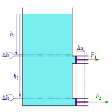
The work done by the piston is fed by the pressure energy, which in the picture is created by the gravitational pressure of the water column.
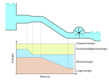
Effect of the partial terms of Bernoulli's equation in the piping system of a dam
Extensions of the classical formulation
The derivation of Bernoulli's equation from the Navier-Stokes equations leads to the general Bernoulli equation in the form
In it are:
- u the speed
the pressure function corresponding to the specific enthalpy in isentropic flow or p / ρ in incompressibility,
- V is the specific position energy, which in the Earth's gravitational field takes the form V = g z,
- η is a loss term which leads to the pressure loss pV = ρ η in incompressible flow and to the loss height HV = η / g in the earth's gravitational field, and
a contribution that occurs only in unsteady flow.
The individual terms of this general Bernoulli equation are the subject of the following sections.
Extended Bernoulli pressure equation of viscosity-free, ideal gases
The Bernoulli equation given at the beginning is only sufficiently accurate for fluids with negligible density change. For gases and larger velocity changes, the density changes associated with the pressure change must be taken into account in the energy approach:
The following formulations are available for the dependence of density on pressure:
- In the case of isothermal or isenthalpic change of state, ρ
with specific gas constant Rs and absolutetemperature T. Thus, relative to a reference point 0:
In this, ln forms the natural logarithm.
- In the case of an isentropic or adiabatic change of state, ρ
with the isentropic exponent κ relative to a reference point 0 and thus
The differential of the specific enthalpy h is dh = T ds + v dp. In this, T is the absolute temperature, s the specific entropy and v = 1/ρ the specific volume. For isentropic flow (ds = 0), dh = dp/ρ and the integrand in Bernoulli's equation above corresponds to the specific enthalpy. Thus the Bernoulli equation for real gases in isentropic flow is:
In this, 
For pressure-driven equalising flows through converging nozzles, the following relationships apply. The specific enthalpy for an ideal gas is h = cp T and with the relationships found in ideal gases 
Where cp,v are the specific heat capacities of the gas at constant pressure and constant volume respectively.
The figure shows the enthalpy contributions h / h0 with h0 = Rs T of air according to the given formulae and isentropic change of state (except for isothermal change of state) relative to the reference point 0 under normal conditions
For the orange curve "h = cv T" 

Extended Bernoulli energy equation of viscous fluids
The extended Bernoulli energy equation deals with viscous fluids. Frictional losses are taken into account. The so-called loss height HV is empirically mostly calculated by a pressure loss coefficient 
with
ζ: Pressure loss coefficient
u: Speed
g: gravitational acceleration (i.e. position energy V = g z)
This assumption is based on the empirical observation that the pressure losses in pipelines in turbulent flow increase with the square of the flow velocity. The loss coefficients or the sum of the loss coefficients in an overall system are composed of:
- Individual losses such as inlet and outlet loss, installation loss (manifolds, constrictions, gate valves) and
- Losses from pipe friction
The pressure equation extended by the pressure loss ρ g HV is therefore:
With this equation, the usual questions of dimensioning piping systems with turbulent flow can be solved if the loss coefficients are known.
For the calculation of energy losses, a distinction would have to be made between individual losses and losses in straight pipes.
Individual losses
These are calculated according to the formula
calculated. The pressure loss coefficients ζ are, for example
- for inlets in pipelines:
ζ = 0.50 (vertical inlet, sharp-edged),
ζ = 0.06 to 0.005 (vertical, rounded inlet),
- in the event of sudden cross-sectional expansion F1 → 2
or
- In case of gradual narrowing (angle of narrowing < 20°)
ζ = 0,04.
The parameter ζ is determined according to empirical formulae which depend on the roughness of the pipeline and the flow behaviour of the medium, see pipe friction coefficient.
Losses in straight pipelines
According to the so-called Darcy-Weisbach equation, these become


calculated.
Extended Bernoulli energy equation for unsteady flows
The contribution of velocity changes with time is usually suppressed in Bernoulli's equation, but can be taken into account:
The integral of the local acceleration ∂ 
The equation is simplified considerably if the flow is loss- and rotation-free or - equivalently - a potential flow. Then there is a velocity potential φ whose gradient is the velocity: 
even globally, i.e. for any points in the flow field. The constant quantity C at a point in time in the entire flow field could still depend on time, but this time dependence can be added to the potential φ without 
Bernoulli equation in rotating reference frame
In technical applications, especially in turbomachinery, reference frames rotating
The vector 
With incompressible flow and rotation about a perpendicular axis in the z-direction, the special shape is created
Where r is the distance from the axis of rotation, ω is the angular velocity and g is the acceleration due to gravity.
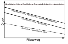
Diagram of the pressure curve in a lossy pipeline
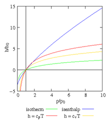
Enthalpy as a function of pressure
Derivation
Derivation from the energy theorem
Bernoulli's equation can be derived from the energy balance, which requires that in a steady flow, work must be done to change the energy of a fluid element. The work is that of the pressure and the energies are the position energy and the kinetic energy. It can then be seen that the sum of the pressure work (somewhat imprecisely pressure energy), the kinetic energy and the position energy is constant along a streamline.
| Derivation via the energy balance |
| The energy balance states that work must be done to change the energy of the fluid elements: W = ΔEpot + ΔEkin In this, W is the mechanical work that must be expended to generate the energy differences ΔEpot/kin between the states 2 (after) and 1 (before). The mechanical work W is the work of pressure required to move a mass m = ρ V with density ρ from the volume V with pressure p1 into the space with pressure p2. The necessary force F is exerted by the pressure difference at points 1 and 2 on the cross-sectional area A1: F = (p1 - p2) A1, see picture. This is because the pressure p2 also acts at the right end of the fluid ball 1. In order to push the whole mass out, this force must work along the path s1 with V = A1 s1: W = F s1 = (p1 - p2) A1 s1 = (p1 - p2) V The difference of the position energy after and before is ΔEpot = ρ V g (h2 - h1) with the heights h1,2. The difference of the kinetic energy after and before is ΔEkin = ½ ρ V (u2² - u1²) with the velocities u1,2. Inserting these intermediate results into the energy balance provides: (p1 - p2) V = ρ V g (h2 - h1) + ½ ρ V (u2² - u1²) Division by the volume V and conversion leads to Bernoulli's equation: p1 + ρ g h1 + ½ ρ u1² = p2 + ρ g h2 + ½ ρ u2² |
Derivation from the Navier-Stokes equations
Today, the Bernoulli equation can be derived from the Navier-Stokes equations for a barotropic, Newtonian fluid in a conservative gravitational field. The assumptions made allow the pre-integration of the gradients occurring in the Navier-Stokes equations along a streamline, which leads to the Bernoulli equation. Since the pressure-density relation for gases is temperature-dependent - gases are generally not barotropic - and liquids are often incompressible to a good approximation, incompressibility is usually assumed. This is given in good approximation for flows far below the wave propagation velocity in the fluid, see figure.
| Derivation from the Navier-Stokes equations |
| The flow of a barotropic Newtonian fluid in a conservative gravitational field is considered. Newtonian fluids obey the Navier-Stokes equations Where In an incompressible fluid, the density is constant and P = p / ρ. In a conservative acceleration field Integrating this equation at a fixed time t along a streamline γ The loss term η is difficult to determine exactly for real flows, but it can be estimated. For a function is only dependent on location, the following applies in The indices 1 and 2 mark the values at the points After conversion, the extended Bernoulli equation given in the text is obtained: In a steady flow the remaining integral on the right-hand side is omitted, in viscosity-free flows the loss term η disappears, in the earth's gravitational field V = g z and in the case of incompressibility P = p / ρ. |
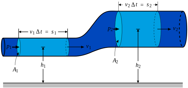
Fluid bales (light blue) in a stream thread (royal blue)
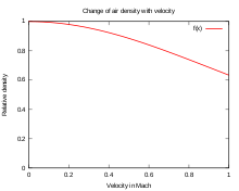
Up to Mach 0.3, the change in air density with velocity is less than 5 % and therefore incompressibility can be assumed at lower velocities.
Example
A container like the one in the picture is located in the homogeneous gravitational field of the earth with gravitational acceleration g and ambient pressure p0 and is filled with an ideal, incompressible liquid with density ρ. The difference in height between the surface AB and the outflow o between F and D is h and the diameter FD is negligibly small in comparison to the surface AB and the height h. At time t0 = 0, the outflow is opened so that the container flows out in a transient flow, whereby the filling level of the container is kept constant by an inflow. The discharge velocity in the outflow pipe is sought as a function of time.
At a time t > t0 a current thread connects the surface AB (point 1) and the outflow o (point 2). The velocity in the vessel ACGB can be neglected because of the small diameter FD compared to AB and the velocity on the cross-sections in the outflow pipe between EG and FD (over the distance L) is everywhere equal to u and likewise its change ∂u/∂t in the outflow pipe is constant. The extended Bernoulli equation for unsteady flows thus yields:
This first order non-linear ordinary differential equation can be solved by separating the variables:
In this, artanh is the atangent hyperbolicus and tanh its inverse function tangent hyperbolicus. The velocity has the value zero at time t = 0 and asymptotically reaches the limit 
This law results from Bernoulli's equation faster with the assumption of a stationary flow:

Bernoulli's Fig. 72 with an outflowing container
See also
- Current thread theory
- Flows in pipelines
- Flows in open channels
Bernoulli effect:
- Bādgir
- Coandă effect
- Lens (optics)
- Airspeed indicator
- Harmonica instrument
- Cavitation
- Sail
- Suction (suction effect)
- Teapot effect
Questions and Answers
Q: What is Bernoulli's principle?
A: Bernoulli's principle is a fluid dynamics concept stating that as the speed of a fluid increases, the pressure decreases.
Q: How is Bernoulli's principle demonstrated in the photo on the right?
A: The photo shows that the air in the wide part of the tube has a higher static pressure than the thin part, causing the fluid speed in the thin part to increase.
Q: What is pressure?
A: Pressure is a force acting over an area.
Q: What happens when a fluid's speed changes?
A: A change in a fluid's speed must be matched by a change in pressure or force.
Q: Does Bernoulli's principle apply to two different flows at different speeds?
A: No, Bernoulli's principle only applies to changes in speed and pressure along a single path of flow.
Q: What does the full version of Bernoulli's principle include?
A: The full version of Bernoulli's principle includes both the work by the pressure and by the changes in potential energy from changes in height.
Q: What does Bernoulli's principle not consider?
A: Bernoulli's principle does not consider viscosity or compressibility.
Search within the encyclopedia


![{\displaystyle {\begin{aligned}\underbrace {e} _{\begin{array}{c}{\text{spezifische}}\\[-1ex]{\text{Gesamtenergie}}\end{array}}=&\underbrace {\frac {u^{2}}{2}} _{\begin{array}{c}{\text{spezifische}}\\[-1ex]{\text{Geschwindigkeits-}}\\[-1ex]{\text{energie }}e_{\text{k}}\end{array}}+\underbrace {\frac {p}{\rho }} _{\begin{array}{c}{\text{spezifische}}\\[-1ex]{\text{Druckenergie}}\\[-1ex]w_{\text{p}}\end{array}}+\underbrace {g\,z} _{\begin{array}{c}{\text{spezifische}}\\[-1ex]{\text{Lageenergie}}\\[-1ex]e_{\text{p}}\end{array}}\\=&{\text{konstant entlang einer Stromlinie}}\end{aligned}}}](https://www.alegsaonline.com/image/f94d115b42387f8f05947b54293a0a8390c82776.svg)


![{\displaystyle {\begin{aligned}\int {\frac {\mathrm {d} p}{\rho (p)}}=&{\frac {\kappa }{\kappa -1}}{\frac {p_{0}}{\rho _{0}}}\left[\left({\frac {p}{p_{0}}}\right)^{\frac {\kappa -1}{\kappa }}-1\right]\\\rightarrow \;e=&{\frac {u^{2}}{2}}+{\frac {\kappa }{\kappa -1}}{\frac {p_{0}}{\rho _{0}}}\left[\left({\frac {p}{p_{0}}}\right)^{\frac {\kappa -1}{\kappa }}-1\right]+V\\=&{\text{konstant entlang einer Stromlinie}}\end{aligned}}}](https://www.alegsaonline.com/image/6660bb36aab6b581baa32e951d2419db15d1246b.svg)


![{\displaystyle {\frac {\partial {\vec {u}}}{\partial t}}+({\vec {u}}\cdot \nabla ){\vec {u}}=-{\frac {\nabla p}{\rho }}+{\vec {k}}+{\frac {1}{\rho }}[\mu \Delta {\vec {u}}+(\lambda +\mu )\nabla (\nabla \cdot {\vec {u}})]}](https://www.alegsaonline.com/image/98517c537814b1527e94cad2bae85ede6e73611b.svg)


![{\displaystyle \nabla \left({\frac {1}{2}}{\vec {u}}\cdot {\vec {u}}+P+V\right)+{\frac {\partial {\vec {u}}}{\partial t}}={\frac {1}{\rho }}[\mu \Delta {\vec {u}}+(\lambda +\mu )\nabla (\nabla \cdot {\vec {u}})]+{\vec {u}}\times (\nabla \times {\vec {u}})}](https://www.alegsaonline.com/image/308968509debcdc1ac1c9f0f22a1e37796d663fb.svg)
![{\displaystyle \gamma \colon s\in [s_{1},s_{2}]\mapsto {\vec {x}}(s)}](https://www.alegsaonline.com/image/49eac0471cb1fa1ef2b1297e90d9304a9b5c12b5.svg)

![{\displaystyle {\begin{aligned}\int _{\gamma }\nabla \left({\frac {1}{2}}{\vec {u}}\cdot {\vec {u}}+P+V\right)\cdot \mathrm {d} {\vec {x}}+\int _{\gamma }{\frac {\partial {\vec {u}}}{\partial t}}\cdot \mathrm {d} {\vec {x}}\qquad \qquad \qquad \\=\int _{\gamma }{\frac {1}{\rho }}[\mu \Delta {\vec {u}}+(\lambda +\mu )\nabla (\nabla \cdot {\vec {u}})]\cdot \mathrm {d} {\vec {x}}=:-\eta \end{aligned}}}](https://www.alegsaonline.com/image/e93abfc8150497c5b2da1bdad6f028218be5bd5f.svg)


