Unified Modeling Language (UML): overview, diagrams, history and uses
UML is a standardized visual modeling language for specifying, visualizing, constructing and documenting software-intensive systems. This article explains its components, history and typical uses.
The Unified Modeling Language (UML) is a standardized, general-purpose visual language for modeling software-intensive systems. It provides a set of notation conventions and diagram types that help architects, developers and analysts express system structure, behavior and interactions in a technology-agnostic way. UML is intentionally independent of any single development process: it can be used alongside iterative, agile, or plan-driven approaches to capture requirements, design elements, interfaces and runtime behavior.
Image gallery
5 Images


Origins and standardization
UML originated in the mid-1990s when several notation families and object-oriented methods were unified into a single language by Grady Booch, Ivar Jacobson and James Rumbaugh while at Rational Software. The language was proposed to reduce fragmentation in software design notation and to provide a common set of concepts for modeling. The Object Management Group (OMG) adopted UML as a standard in 1997, and the language has evolved under OMG stewardship. Major revisions produced UML 2, which expanded diagram semantics and added new constructs; the language was also published as an international standard by ISO in the 2000s.
Core elements and diagram types
UML organizes its notation around structural and behavioral concerns. Structural diagrams depict the static organization of a system, while behavioral diagrams describe dynamic aspects. Common diagram categories include:
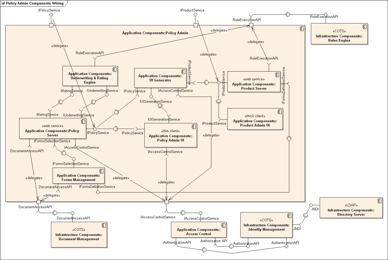
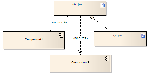
- Structural diagrams: class, component, package, object, and deployment diagrams.
- Behavioral diagrams: use case, activity and state machine diagrams that capture workflows and lifecycle behavior.
- Interaction diagrams: sequence, communication and timing diagrams that show message flows between parts of a system.
Each diagram type uses a small set of modeling constructs—such as classes, attributes, operations, actors, actions, states and messages—that can be combined to form higher-level views of a system. The consistent semantics allow diagrams to complement each other: for example, a class diagram describes structure while corresponding sequence diagrams illustrate how operations are used at runtime.
Common modeling elements
Some frequently used UML concepts are:
- Class and object: templates and instances that define data and behavior.
- Relationships: associations, aggregations, compositions, generalizations (inheritance) and dependencies between model elements.
- Interfaces and components: modular boundaries and provided/required contracts.
- Actors and use cases: external roles and the services they require from the system.
Uses, examples and practical value
UML is used to communicate ideas among stakeholders, to document systems for maintenance, and to drive design decisions. Typical applications include modeling system architecture, describing APIs, specifying workflows and capturing requirements as use cases. UML diagrams can also assist reverse engineering by providing higher-level views extracted from code, and some tools support forward or round-trip engineering, generating skeleton code from models or updating models from code changes.
Tools, limits and adoption notes
A wide range of modeling tools support UML, from lightweight drawing apps to integrated modeling environments. UML is not a development methodology itself: it is a language that can be applied within processes such as the Rational Unified Process, Scrum, or bespoke practices. Practitioners emphasize tailoring: choose diagram types and levels of detail appropriate to stakeholder needs, avoid excessive or out-of-date documentation, and use models as communication aids rather than as an end in themselves. For governance and further resources see the Object Management Group at OMG and the ISO publication references at ISO.
Questions and answers
Q: What is the Unified Modeling Language (UML)?
A: The Unified Modeling Language (UML) is a modeling language used in software engineering to provide a standard way of showing what the design of a system looks like.
Q: What was the original purpose of UML?
A: The original purpose of UML was to standardize the different notational systems and approaches to software design.
Q: Who developed UML?
A: UML was developed by Grady Booch, Ivar Jacobson, and James Rumbaugh at Rational Software in 1994-1995, with further development led by them through 1996.
Q: When was UML adopted as a standard?
A: UML was adopted as a standard by the Object Management Group (OMG) in 1997.
Q: Who manages UML?
A: UML has been managed by the Object Management Group since its adoption as a standard in 1997.
Q: Was UML recognized as an international standard?
A: Yes, UML was recognized as an international standard by the International Organization for Standardization (ISO) in 2005.
Q: What is the purpose of UML in software engineering?
A: The purpose of UML in software engineering is to provide a standard way to show what the design of a system looks like, so that it can be easily understood and communicated among developers and stakeholders.
Related articles
Author
AlegsaOnline.com Unified Modeling Language (UML): overview, diagrams, history and uses Leandro Alegsa
URL: https://en.alegsaonline.com/art/102752