Turbine
![]()
This article is about the machine. For other meanings, see Turbine (disambiguation).
A turbine (Latin turbare 'to turn') is a rotating fluid machine that converts the dissipation of the internal energy of a flowing fluid (liquid or gas) into mechanical power (torque times speed), which it delivers through its shaft.
By flowing around the turbine blades with as little turbulence as possible (laminar flow), part of the internal energy of the fluid flow (mostly consisting of kinetic, positional and pressure energy) is extracted and transferred to the turbine blades. Via these, the turbine shaft is then set in rotation, and the usable power is delivered to a coupled working machine, such as a generator.
Power plant turbines are among the most powerful machines. Today, their mechanically usable power reaches almost 1.8 gigawatts in the largest nuclear power plants. In the case of large outputs, a turbine consists of several partial turbines (high-, medium- and low-pressure turbine(s)). The steep torque characteristic of the generator ensures a constant speed of the power plant turbine, otherwise the speed must be kept constant via a governor.
Colloquially, the term turbine is also used for jet engines, although the turbine is only one part of the engine; the engine also consists of a compressor, combustion chamber and other components.
The term "turbine" was coined by the French engineer Claude Burdin.

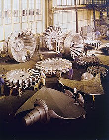
Three types of water turbines: Kaplan blade (front), Pelton wheel (middle), Francis turbine (back left).
Basics
![]()
This section does not separate well enough between a single impeller and an overall turbine, which includes other components involved in power conversion - for example, the guide vanes or the flow channel cross-section; in addition, turbines are sometimes multi-stage. The section needs some revision. More details should be given on Discussion:Turbine. Please help improve it, and then remove this tag.
Theory
The theoretical foundations for calculating any type of turbine were laid as early as the 18th century by Leonhard Euler.
Euler's turbine equation
The basis of Euler's turbine equation is found in the conservation of angular momentum of a material flow in a closed system:
The change of momentum within a subsystem (here: the turbine blades) generates a torque around the centre of the turbine:
It makes sense that only those parts of the flow velocity of the fluid can contribute to the torque that are perpendicular to the turbine's centre of rotation in the sense of the law of levers. Such components are marked with the index u.
An integration of the formula gives the following result:
From the relationship between torque, the speed 

with 
A new integration provides

The last equation is called Euler's turbine equation. Its solution is given by:


In reality, the friction losses of the flowing fluid must also be taken into account for the approximate turbine design.

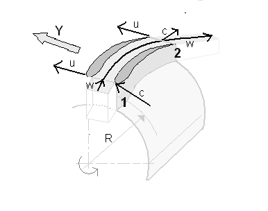
Perspective representation of the physical quantities for Euler's turbine equation

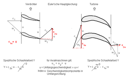
Application of Euler's turbine equation to axial flow machines
Engineering
![]()
This section applies to gaseous fluid turbines only and contains physical errors; needs revision. More details should be given on the discussion page in the Revert section as of 5/6/2019. Please help improve it, and then remove this marker.
As a rule, several blades are mounted on a hub, so that a blade or impeller is formed. The blades are curved profiled, similar to an aircraft wing.
If turbines are mounted in a flow-through casing, there is a guide wheel in front of each impeller stage. The guide vanes project from the casing into the flowing medium and impart an angular momentum (twist) to it. The twist (kinetic energy) generated in the guide wheel is dissipated as completely as possible in the following impeller in order to drive the shaft on which the impeller blades are mounted via the hub. The rotation of the shaft can be used to drive a generator, for example. Ultimately, this is how the mechanical flow energy of water power, steam or air is converted into electrical energy. The guide wheel and impeller together are called a stage. In gas turbines and especially in steam turbines, several such stages are connected in series, while water turbines have a single stage. Since the stator is stationary, its vanes can be attached to either the inside or the outside of the casing, thus providing a bearing for the shaft of the impeller. Free-standing turbines (e.g. wind turbines) usually have no guide vanes and only one stage. The impellers are decisive for the stage classification - each is the basis of its own stage.
Turbines can be directly coupled to high-speed generators that convert the mechanical rotational energy into electrical energy. These high-speed, low-pole generators are also called turbogenerators. A combination of turbine and turbogenerator is called a turbo set.
If a turbine is driven by means of a compressor and a combustion system for gas or oil, the overall system is called a "gas turbine". Gas turbines are used, for example, in aircraft, ships or in gas and oil-fired power plants. Turbine jet engines are gas turbines that power aircraft wholly or partly by the recoil of their accelerated exhaust gases (thrust). Jacketed jet engines generate a larger part of the thrust by means of a turbine-driven fan ("fan").
Special cases
There were wind turbines that were designed with only one rotor blade (and one counterweight), the so-called single-winged turbines.
The Ljung flow turbine is a design of steam turbine without guide vanes. The turbine, through which the flow passes radially from the inside to the outside, consists of two intermeshing halves which rotate in opposite directions. The impeller blades of one half act as guide vanes for the other half. In the Pelton and Laval turbines, the guide vanes are reduced to one or more nozzles.

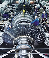
Assembly of a steam turbine
Search within the encyclopedia


