Triode
An electron tube is an active electrical component with electrodes located in an evacuated or gas-filled bulb made of glass, steel or ceramic. The terminals of the electrodes are led out of the tube bulb to the outside. In its simplest form as a diode, an electron tube contains a heated cathode (hot cathode) and an anode. Electron tubes are used to generate, rectify, amplify or modulate electrical signals.
Negatively charged elementary particles emerge from the hot cathode as free electrons and are moved to the anode by the effect of an electric field. This electron flow can be influenced by a control grid between cathode and anode, because the electron flow is inhibited more or less by different grid voltages or electric fields. This is the basis for the use of the electron tube as an amplifier or oscillator.
Electron tubes were the only fast active (controllable) components in electronics until the introduction of the transistor. Until then, only transducers and relays were available as active two-port devices, whereby the latter only knew two states (on/off) and their switching speed was limited by the moving mass. Electrons have a much lower mass, therefore much higher frequencies can be processed with their help.
Depending on the type of tube, a low-pressure gas may be included to provide additional ionic conduction and compensate for the effect of the space charge.
Even today, tubes are still used in many fields. Powerful transmitters are operated with electron tubes, magnetrons are used in radar systems and microwave ovens. Older television sets and computer monitors use cathode ray tubes. Tube amplifiers are also still used as audio amplifiers at the high end. Many electric guitarists and bassists also appreciate the characteristic sound of a tube amplifier. Fluorescent displays are used to visually signal the status of devices such as CD players, video recorders and so on, but are increasingly being replaced by liquid crystal displays and organic light-emitting diodes.
Several types of tubes with corresponding demand are still produced today, mainly in Russia and China. Some are also still available from old (military) spare parts stocks (New Old Stock).
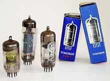
Radio tubes: ECC85, EL84 and EABC80.
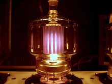
Transmitter tube in operation
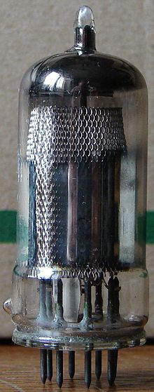
Rimlock pentode EF42
History
The physical chemist Frederick Guthrie discovered incandescent emission in 1873, but without any practical effects. In 1880, the effect was observed again by Thomas Alva Edison during experiments with incandescent lamps independently of Guthrie. The observation was made with incandescent lamps that contained an additional electrode in the glass body. Edison realized that the flow of electrons between the filament and the electrode increases with the heating current. This law was subsequently named the Edison-Richardson effect. The first electronic circuit to exploit this relationship was a DC voltage regulator, which Edison patented in 1883.
The vacuum diode was patented in 1904 by the English physicist John Ambrose Fleming. In his search for an improved detector for radio waves, Fleming discovered that the Edison-Richardson effect could be used for detection or rectification.
The Austrian physicist Robert von Lieben developed a mercury vapour-filled amplifier tube with two electrodes and electrostatic or electromagnetic influence from outside - the so-called Lieben tube - and applied for a patent for it as a cathode ray relay at the Imperial Patent Office of the German Empire on March 4, 1906. Together with Eugen Reisz and Sigmund Strauß, whose primary goal was a telephone amplifier, Lieben explicitly formulated the amplification of the electrical signal as the purpose of the invention in his patent.
Independently of Lieben, the US inventor Lee de Forest developed the audion tube and applied for a patent for this gas-filled tube, which had an additional third electrode as a control grid, on October 25, 1906. Lieben and De Forest later engaged in a legal dispute that lasted for years.
De Forest presented a tube amplifier to Bell Telephone Laboratories in October 1912. Within a year, this was made marketable by succeeding in creating a high vacuum in the tubes. Harold D. Arnold of Western Electric used a vacuum pump designed by Wolfgang Gaede. Irving Langmuir of General Electric also used a cold trap with liquid air. In 1913, the Type A high vacuum triode was built at Western Electric. Pliotron was the name General Electric chose for its first high vacuum triodes. The first tube amplifiers were used in late 1913 for telephone connections between New York and Baltimore, and from late 1914 to amplify signals on the Atlantic submarine cable.
In 1914, the Lieben consortium patented a mercury vapor-filled tube with a control grid and heat protection jacket as a switching amplifier in radio telegraphy. Despite these efforts for gas-filled tubes, vacuum tubes prevailed in these applications as well.
At Siemens & Halske in Germany, Walter Schottky developed the tetrode (screen grid tube) in 1916. The early tetrodes - like the SSI of 1917 - had better amplification than triodes, but were only suitable for low frequency amplifiers.
Henry Joseph Round developed the high-frequency triode V24 at the Marconi Company in England in 1916. HF amplifiers for radio direction finding were used by the British side in the Battle of Skagerrak in 1916.
In 1919, Eduard Schrack produced the Triotron radio tube he had developed on an industrial scale for the first time. For this purpose, he built a production facility in Vienna. He is considered the father of the Austrian radio industry.
Hendrik van der Bijl from South Africa developed the first miniature tube in 1919, which was distributed by Western Electric as 215A from 1923. RCA distributed the 955 acorn tube from 1934 as the first all-glass tube. The all-glass design allowed operation into the UHF range, which was important for radar systems. Further miniaturization led to the pencil-thick DF70 subminiature tube for hearing aids in 1948.
The French company Métal produced from 1924 the double grid tube (Bigrille) RM as a mixing tube, which were used especially in radio receivers of the company Eugène Ducretet (today Thales Group). The development of mixing tubes for frequency conversion from radio frequency to intermediate frequency in the superhet led, among other things, to the multi-system tubes ECH4 and ECH81 (1952), which contained a triode for operating the mixing oscillator and a heptode for mixing.
At the Philips laboratory in Eindhoven, Bernard Tellegen developed the pentode to production maturity in 1926. The NF end pentode B443 was available from 1927. The pentode became the standard amplifier element of the tube era. In the input stage of VHF and TV receivers, however, after some experiments with pentodes, triodes in cascode circuit were used again, since they do not exhibit current distribution noise. Pentodes and beam power tetrodes were used in the output stage of low frequency amplifiers.
In 1926, Manfred von Ardenne, together with Siegmund Loewe (patent holder) in Germany, developed one of the first multi-system tubes, the so-called triple tube type 3NF, which, in addition to three triode systems, also housed four resistors and two capacitors. It was a kind of integrated circuit and was used in the radio receiver Audion OE333.
In radio receivers, amplifiers and televisions, electron tubes were gradually replaced by transistors from the late 1950s onwards. Some consumer electronics equipment remained at least partially tube-based until the 1970s. The picture tube of televisions and computer monitors was not replaced by devices with liquid crystal displays or OLEDs until the 2000s.
Because of their resistance to cosmic rays, ionizing radiation from nuclear weapons, and EMP, amplifier tubes continued to be developed in the aerospace and military fields until the 1970s, especially in the USSR. A MiG-25 fighter has numerous subminiature tubes; these tubes were often encased in lead sheets.
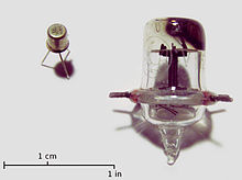
Acorn tube 955 from RCA, with transistor for size comparison
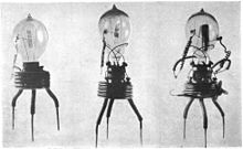
First prototype of the vacuum diode by Fleming, around 1905
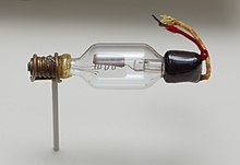
One of the first triodes by Lee de Forest (1906). The metal plate on top is the anode, the meandering wire underneath is the control grid. The filament (cathode) was stretched between the four holding wires underneath, but is glowed through.
Mechanical structure
The classic high-vacuum electron tube consists of a closed bulb in which the electrode system is installed. Feedthrough wires establish the electrical connection with the circuit.
The substances of the individual parts must be of a high purity. Depending on the combination, even traces of foreign substances can significantly impair the service life of a finished tube. During the shaping process, cleaning steps are carried out again and again, be it by mechanical processing, annealing, oxidizing or dissolving the unwanted surface layers.
Cleanliness is essential both during the manufacture of the individual parts and during assembly. Grease and sweat of the hand, dust, lint of the environment have a long-term effect on vacuum degradation in later manufacturing steps or chemical compounds are formed by the heating, which later impair the emissivity of the cathode.
External structure
Start times
In the early days of the tubes, the bulb was made exclusively of glass. The horizontal electrode system was welded to stable holding wires in a crimp base. These holding wires were led through the crimp connection with lead-through wires and finally threaded into a base made of Bakelite and soldered to its contacts. The base was cemented to the glass bulb. This construction was a direct development of the incandescent lamp production and enabled a sufficiently stable construction of the system.
The particular challenge is to achieve a vacuum-tight connection between the feedthrough wire and the flask. In the course of time, composite metal wires such as Fernico were developed here, which are well wetted by the glass mass during the melting process and thus leave no significant gaps for diffusion of gas molecules. The glass mixtures were also further developed until the thermal expansion of the lead wire and the glass bulb differed only insignificantly.
Over time, the cantilever mounting was abandoned because the electrodes in the tube system were very susceptible to microphonics. Instead, the dome flask was established. Its height was exactly adapted to the height of the now vertically mounted electrode system; mica wings were attached to the top of the system structure, which pressed laterally against the piston wall and thus fixed the system in the piston with little vibration.
This pinch-foot design resulted in comparatively long connecting wires. Their self-inductance as well as capacitance due to the parallel routing of the wires into the bulb prevented these tubes from being useful in the VHF frequency range and above. An extensive decoupling of the grid connection via a connection cap attached to the piston head complicated the production of the tubes, but also made higher amplifications possible.
Parallel to the glass bulb, tubes with steel bulbs were also built.
→ Main article: Steel tube
Later construction
Even during the steel tube era, glass tube development did not stop. The further refinement of manufacturing techniques made it possible to significantly reduce the dimensions of the bulbs:
| Tube | Height | Diameter |
| EF12 | 58 mm | 47 mm |
| RV12P2000 | 43 mm | 27 mm |
The most prominent example is the RV12P2000, which again features a vertical system design in a cylindrical glass bulb. The mechanical fixation of the system is provided by mica plates with a feathered outer edge attached to the upper and lower sides of the system, which largely prevent lateral oscillation in the bulb. A fundamental innovation worth mentioning is the use of a pressed glass plate for the connection bushings, which replaced the conventional, high-frequency problematic squeeze-foot design.
Under increasing pressure of manufacturing costs, the usual all-glass tube with pressed glass base emerged in the early 1940s. The very short connecting pins made of chrome iron or nickel allow the range of application of this socketing to extend into the UHF range and, through stable welded connections with the rest of the system, enable position stabilization even in the vertical. This design was introduced in the early 1940s with the Loktal tubes (Philips, Tungsram) and further miniaturized with the Rimlock tubes (Philips/Valvo, 1947).
The miniature base introduced in 1940 and the noval base established in 1951/52 indicate the correct alignment in the socket by a gap in the pin circle without external aids and are still the state of the art for small signal tubes today.
Tubes of higher power often have a less vibration-free construction because of better insulation and material cost savings. Thus with transmitter tubes (and with high voltage tubes, PD500, DY8...) the anode is often only fixed by a lead-through through the glass bulb. Due to the generally larger electrode distances in these tubes, any mechanical oscillation of the electrodes does not have as strong an effect as in small signal tubes.
There were also further developments in ceramic technology, which resulted in the Nuvistor tubes, which were only the size of a thimble. At this time, however, semiconductor technology was already so far on the advance that these types could no longer spread to any significant extent.
Internal structure
In the early days, the actual electrode system of the tube was mounted cantilevered on the crimping foot. In individual cases, a glass bridge was incorporated above the tube system, which was also intended to ensure that the tube electrodes were seated true to size from above. Later, the dome piston design was changed to a ceramic bridge-based design, since the glass bridges were lossy, increased capacitance and did not noticeably reduce the sensitivity to microphonics. The individual system components, such as the grid and cathode, are inserted with their ends into recesses in the bridges and thus fixed against lateral slippage. However, the ceramic components had a very high tendency to emit secondary electrons, which is why mica plates made of muscovite were soon used instead of ceramics. Moreover, there is no need to consider thermal expansion issues of the electrodes because mica is elastic to a small extent compared to ceramics. For the same reason, the punched holes in the mica plates can be rather narrow, so that the electrodes fit very tightly, which in turn prevents mechanical vibrations (microphonics). Finally, the anode, which is usually cylindrical or box-shaped, serves as a horizontal fixation of the mica plates to each other.
The following table shows how much miniaturization has progressed in just a few years:
| AF7 (1935) | EF12 (1938) | |
| Cathode-ø | 001.8 mm | 000.8 mm |
| Distance k - g1 | 000.40 mm | 000.23 mm |
| Distance g1 - g2 | 001.05 mm | 000.55 mm |
Most electrode systems are concentric in design. The completely assembled system is spot welded to the base connections and the piston is then fused to the base plate or pinch foot.
Further details on the mechanical construction can also be found in the sections on the cathode, anode and the other electrodes.
Evacuation
The tube must now be pumped out. The vacuum in the tube is necessary so that the electrons have a sufficient free path length and are not slowed down by gas molecules.
After the tube plungers have melted off, the tube is connected to a vacuum pump via the pump tube. During the pumping process, the so-called bake-out begins at a certain negative pressure in the tube. For this purpose, the tube is heated by means of its own heating filament; at the same time, a powerful high-frequency field (several 100 kHz), similar to an induction hob, is used to selectively cause the metallic inner parts of the tube system to glow, while the getter is left out. The process is used to remove the gas molecules, which are physically bound by adsorption on the surfaces and by Van der Waals forces, more quickly and to pump them out with the gas. This shortens the evacuation time, improves the quality of the vacuum remaining over the planned lifetime of the tube and thus reduces the use of getter material.
In order to maintain the quality of the vacuum over the operating time, it is essential that the tube is not exposed to higher temperatures during regular operation than during bake-out. There may well still be gas residues in the individual electrode parts, but these could only be baked out at higher temperatures. The bakeout temperature is a compromise between economy (bakeout duration and temperature: power consumption of the HF generators and pumps), vacuum quality over the service life and avoidance of damage (softening and warping of the bulb glass or internal electrodes due to excessively high temperatures). If the tube is overloaded, the remaining residual gas is expelled (partially, depending on duration and temperature) and permanently worsens the vacuum.
Finally, the pump tube is melted off, leaving behind the characteristic glass cone. The next step is the targeted "ignition" of the getter, which binds gases released during normal operation of the tube or gases diffusing in from outside. On the inner wall of many tubes, a mirror-like coating can usually be seen in the upper part, which is caused by this getter.
If a tube has drawn air through damage, the getter reacts with the gases that have entered. This is visible through the shrinkage of the reflective layer and the remaining milky-white coating. Other getter types, which directly bind possible gas residues without a glass mirror, were used for high-voltage tubes, for example.
Completion of production
The tube is then artificially aged to ensure that its operating parameters remain stable over the expected lifetime. After a final quality control, the tubes are stamped, packed and shipped.
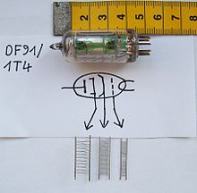
The three grids of a DF91
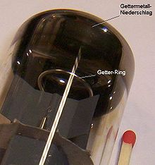
Getter ring and getter mirror in an electron tube, mica plate for electrode fixation
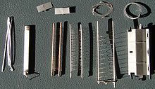
The individual parts of a Valvo-EL84
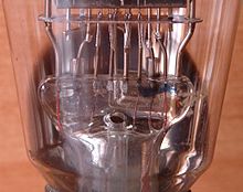
Crush foot assembly of an AL1
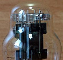
Detail of the dome of an AL1
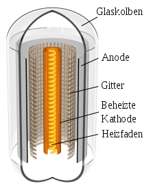
Sectional view through an electron tube (triode)
Questions and Answers
Q: What is a triode?
A: A triode is a type of vacuum tube with three electrodes: cathode, anode, and grid.
Q: How does a triode differ from a diode?
A: A triode has a third electrode called the grid, while a diode only has two electrodes.
Q: What is the purpose of the grid in a triode?
A: The grid controls the flow of electrons between the cathode and anode, allowing for amplification or modulation of a signal.
Q: What is the function of the cathode in a triode?
A: The cathode emits electrons, which are then accelerated towards the anode by a high positive voltage.
Q: What is the role of the anode in a triode?
A: The anode receives the electrons emitted by the cathode and converts them into an electrical signal.
Q: Why is a triode also known as a "valve" in British English?
A: The name "valve" refers to how the triode can control the flow of current like a valve controls the flow of liquid.
Q: Why is a triode referred to as an "empty" tube?
A: A triode is called an "empty" tube because it contains no air or gas and operates in a vacuum.
Search within the encyclopedia