
Torsion (mechanics): twisting of structural members under torque
Torsion is the twisting deformation of a structural member produced by an applied torque. This article explains stress and angle-of-twist formulas, assumptions, practical examples, and limitations.
Overview
Torsion in mechanics describes the twisting of an object about its longitudinal axis when subjected to an applied torque. In engineering practice torsion is a common load case for shafts, rods, beams and fasteners. A simple, widely used model assumes linear elastic material behavior, small deformations, and cross-sections that remain plane and unstretched during twist. For a more detailed treatment see solid mechanics.
Image gallery
3 Images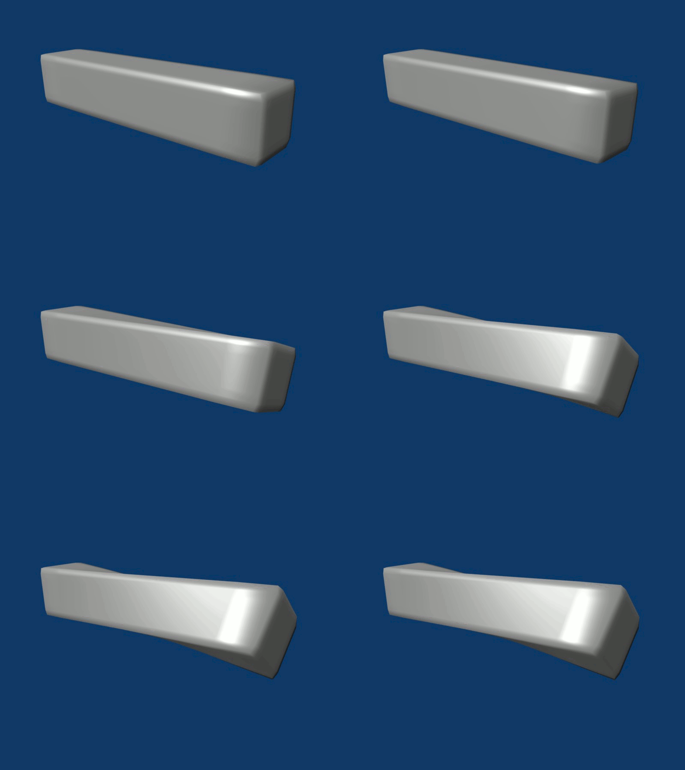


Basic relations and stress distribution
For a circular shaft under torque T, the shear stress at a radial distance r from the center varies linearly with r and is given by the relation τ_θz = T r / J, where J is the polar moment of area (also called polar second moment) of the cross section. The maximum shear stress occurs at the outer radius. The polar moment is defined as J = ∫ r^2 dA for the cross-sectional area. See also general notes on polar moment of inertia.
Angle of twist and torsional stiffness
The uniform angle of twist over a shaft length L under constant torque can be estimated from θ = T L / (G J), where G is the shear modulus of the material. For nonuniform torque distribution the local twist rate satisfies dθ/dx = T(x)/(G J). This relation underpins the design of torsional springs and shafts and connects applied torque to elastic deformation.
Applications, limitations and important distinctions
- Typical applications: drive shafts, torsion bars, couplings, screw fasteners and torque sensors.
- Limitations: the simple circular-shaft formula assumes Saint-Venant conditions—ends sufficiently far from load concentrations—and does not apply to thin-walled open sections or noncircular cross sections where warping occurs. For those shapes one uses Prandtl’s stress function or numerical methods.
- Distinctions: polar moment of area (J) is an elastic-geometric property of a cross section and differs from mass polar moment used in dynamics; torque units are typically N·m while shear stress is in pascals (Pa).
- Extreme loading: beyond elastic limits, torsion leads to yielding and eventually shear failure or ductile fracture; plastic torsion follows different relations.
Further reading and context
For practical design and failure analysis consult materials on shear stress, shaft design and torsional vibration. Introductory references cover the shear stress formula and angle-of-twist derivation; advanced texts address warping, nonuniform torsion and numerical solutions. See entries on shear stress, shaft behavior in shafts and rotors, and foundational mechanics at solid mechanics and polar moment.


Torsional moment of inertia
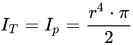
Exclusively for circular and for closed circular ring cross sections, the torsional moment of inertia is equal to the polar area moment of inertia  :
:
For other cross-sections, the calculation of the torsional moment of inertia is only possible in closed form in special cases.
In addition, when determining the torsional moment of inertia, it is often important to know whether the cross-sections are warp-free or not, and whether the warping is impeded or not.
Torsion without warping
For closed sections whose products of wall thickness  and distance
  from the axis of rotation are constant laterally (
  ), shear stresses are produced in the case of torsion, but no normal stresses in the longitudinal direction and thus no warping of the cross-section. These conditions are met, for example, by a cylindrical tube of constant wall thickness. This case of torsion is called Neuber's shell.
However, it should be noted that the linear elasticity theory applies, i.e. only small distortions and deformations are permitted, but no plastic deformations. In addition, the load should be applied in the form of the torsional moment on the longitudinal axis.
The shear stress τ  in the member is given by the torsional moment
  divided by the polar section modulus
  :
:

The maximum shear stress occurs at the edge or at the maximum radius of the cross-section under consideration. When dimensioning, care must be taken to ensure that this shear stress does not exceed the maximum permissible shear stress τ  of the material to be used:

Otherwise, the deformation of a shaft, for example, passes from the elastic range into the plastic range and finally leads to fracture.
Questions and answers
Q: What is torsion?
A: Torsion is the twisting of an object that results from an applied torque.
Q: How is shearing stress related to torsion?
A: In circular sections, the resultant shearing stress is perpendicular to the radius.
Q: What equation can be used to calculate shear stress at a point on a shaft?
A: The equation for calculating shear stress at a point on a shaft is τθz = Tr/J, where T is the applied torque, r is the distance from the center of rotation, and J is the polar moment of inertia.
Q: What equation can be used to find angle of twist?
A: The equation for finding angle of twist is θ = TL/JG, where L represents length and G represents modulus of rigidity.
Q: What does "T" represent in the equations for shear stress and angle of twist?
A: In both equations, "T" represents applied torque.
Q: What does "r" represent in the equation for shear stress?
A: In the equation for shear stress, "r" represents distance from center of rotation.
Q: What does "J" represent in both equations?
A:"J" represents polar moment of inertia in both equations.
Related articles
Author
AlegsaOnline.com Torsion (mechanics): twisting of structural members under torque Leandro Alegsa
URL: https://en.alegsaonline.com/art/100760