Torque
Torque (also moment or moment of force, from the Latin momentum motive force) is a physical quantity in classical mechanics that describes the rotational effect of a force, a pair of forces or other system of forces on a body. It plays the same role for rotational movements as the force does for rectilinear movements. A torque can accelerate or brake the rotation of a body and bend (bending moment) or twist (torsion moment) the body. In drive shafts, the torque together with the speed determines the transmitted power. Each torque can be described by a pair of forces. The torque of a force pair is independent of the reference point and can therefore be shifted as a free vector.
The internationally used unit of measurement for torque is the Newton metre. The 


Here 


If several forces 


If two parallel forces act on a body which have the same magnitude 


Designations and delimitation
Torque as a first-order moment
→ Main article: Moment (integration)
The term "moment" is generally used for characteristic values of distributions that relate to the form
can be brought. For a torque, take for the dimension μ 


Instead of a force distribution, other physical quantities can also be considered and their distributions developed generally according to moments, as in a multipole development. The resulting quantities that are not torques are also designated with words that contain the ending -moment. Examples are the moment of area, the moment of inertia or the magnetic moment.
Word choice in science and technology
In works of theoretical mechanics and physics, the physical quantity dealt with here is quite generally referred to as torque. In technical mechanics as well as in DIN and VDI standards, the quantity is usually generally referred to as torque. Rarely it is also generally referred to as torque, sometimes the term torque is also rejected as "colloquial". Sometimes torque is used for the moment of a pair of forces. Mostly, torque is only used when there is a rotation of the body under consideration, for example when tightening screws or shafts of motors, but not when there is a deformation (bending or torsional moment) or the effect is not yet known (moment).
In the following of this article, the term torque is used in a general sense, synonymous with the moment of engineering mechanics and is not limited to rotary motions or pairs of forces.
In addition, there are a number of torques that are formed with the suffix -moment, such as the bending moment, the torsional moment or the drive moment. Designations such as bending torque or torsional torque do not occur.
In English, the terms torque and moment are possible. The usage differs according to British and US English as well as the technical and physical environment.
Special torques in technology
A distinction is made between
Type of stress:
- Bending moment: A moment that stresses a component to bend.
- Torsional moment: The moment that stresses a component to twist (torsion).
- Cutting moment: Cutting reaction when cutting free.
Type of movement:
- Yaw, pitch, roll moment: moments about specific axes of a rigid body during yaw, pitch and roll.
Nature of the effect:
- Starting torque: The torque that a prime mover can deliver from a standstill (more rarely referred to as breakaway torque) or that a driven machine or vehicle requires when starting.
- Input torque: The torque acting on the input shaft of a driven machine or gearbox, on the wheel axle of a vehicle or on the axle of a propeller. For the driving prime mover or transmission, it is the output torque.
- Tightening torque or torque: The torque applied when fastening (tightening) a bolt.
- Tilting moment: In mechanics, the moment that causes an upright object to tip over. In electrical engineering, the maximum moment in the torque/speed characteristic curve of an asynchronous motor. For details see tipping point.
- Load torque: The torque that a working machine exerts against the driving prime mover or gearbox. For the prime mover or the gearbox it is the output torque.
- Clamping moment: A moment that is generated at the clamping, i.e. the attachment of a body. It prevents rotation of the body.
- Offset moment: Moment of a force with respect to the reference point for the equilibrium of forces and moments.
Other:
- Design moment: The moment for which a component was designed during construction.
- Nominal torque: The torque for which a component was designed.
- Specific torque: The torque per litre of displacement for piston engines. The maximum values for four-stroke petrol engines and for large four-stroke diesel engines are 200 Nm/dm³. Very large two-stroke marine diesels reach 300 Nm/dm³.
Types of torques
A distinction is made between
- the torque of a single force with respect to a point,
- the torque of a single force with respect to an axis and
- the torque of a pair of forces.
With the first two terms, the amount and direction of rotation of the torque depend on the reference piece (point or straight line). In the case of a pair of forces, on the other hand, the same total torque is always obtained, regardless of the reference piece, if the torques of the individual forces of the pair are considered and added together.
For all three types, two different equally valid ways of looking at things are possible:
- A mixed, geometric and algebraic consideration in which the amount of torque results as the product of force and lever arm. The plane of action and the direction of rotation result from geometric considerations.
- The second variant is a purely analytical one. Here, the torque is considered as a vector, which results as the vector product of the location vector and the force vector. The torque vector then indicates the magnitude, the effective plane and the direction of rotation.
Which approach is more appropriate depends on the problem to be investigated and the mathematical knowledge of the user. If all the acting forces lie in the same plane, the geometric-algebraic approach is the most suitable, as it requires comparatively simple mathematics. If the forces form a spatial force system, such a procedure is possible but difficult. The vectorial representation then offers itself, but requires knowledge of more advanced concepts of mathematics such as the vector product. In addition, general mathematical relationships between torque and other physical quantities, such as those studied in theoretical mechanics, are easier to represent with vectors. In textbooks and introductory textbooks on technical mechanics, the geometric-algebraic view is initially preferred. In textbooks on theoretical mechanics and reference works on technical mechanics, on the other hand, the vectorial representation is widespread.
For all three types, the following applies to the amount of torque: force times lever arm. A single torque acts in a plane and it is basically sufficient to consider this plane. The torque can then be indicated by a single number whose sign indicates the direction of rotation. Torques that rotate counterclockwise, i.e. in a mathematically positive sense, are usually counted as positive. In the case of several torques that do not act in the same plane, it is more appropriate to describe them with their torque vector. This is perpendicular to the plane in which the torque acts.
Various ways are possible for the theoretical derivation of torques. Starting from the basic laws of mechanics, the torque of a single force can be defined. The torque of a force pair is then the sum of the torques of the two forces. Instead, considerations of the resultant of a force pair lead directly to its torque. The torque of a single force then results from the displacement of the force to a parallel line of action (offset moment, see displacement of forces below).
Torque of a force with respect to a point
The torque or moment of a (single) force with respect to a point 


To avoid confusion with other torques, the reference point is also noted:


The lever arm is the vertical distance between the reference point and the line of action of the force. This is generally not the direct connecting line between the reference point and the point of application of the force. Since the lever arm does not change when the force is moved along its line of action, its torque does not change either. The reference point itself is freely selectable. It does not have to be the point around which the body under consideration rotates. In some cases, this point is not known and in the case of bodies that are firmly connected to their environment, such a point does not exist. The reference point does not have to be part of the body on which the force acts. Both the amount and the direction of rotation of the torque depend on the choice of the reference point.
The vectorial definition is

It is the vector product of the location vector 


Thus, 
Often the torque is also always referred to the origin 
The position vector 
The torque vector is perpendicular to the plane in which the torque acts and thus also perpendicular to the plane spanned by the force and location vector. Its magnitude, i.e. its length, corresponds to the magnitude of the torque and the area of the parallelogram formed by the position and force vector. The direction of rotation is determined by the right-hand rule: If one grasps the torque vector in thought with the right hand in such a way that the thumb points in the direction of the arrowhead, then the remaining fingers indicate the direction of rotation.
Torque of a force with respect to an axis
For the torque of a force with respect to an axis, the point on the axis closest to the point of application of the force is chosen as the reference point. The distance of the point of application from the axis is then the lever arm. For calculation, one can project the force into a plane that is perpendicular to the axis and then form from the projected force the torque with respect to the point where the axis pierces the plane. Alternatively, the torque of the original force can be formed with respect to any point on the straight line. The torque vector is then projected into a plane perpendicular to the straight line.
Torque of a pair of forces
→ Main article: Force pair
A force couple consists of two forces that are on parallel lines of action, have the same magnitude and point in opposite directions. Unlike a single force, it cannot move a body, but it attempts to rotate it. Pairs of forces are often present when there is rotational movement of bodies; however, one of the two forces is often not immediately apparent because it is usually a constraining force. The amount of torque produced by a pair of forces can be calculated as the product of the magnitude 

The torque vector of the force pair can be calculated by:
The position vector 
The action of pairs of forces differs from individual forces in some important respects, which is why the torques of pairs of forces also differ from other torques:
- The torque of a force pair is independent of reference points. This means that a force pair can be moved to any location without changing its action or torque.
- A pair of forces can be replaced by its torque without changing the effect on the body on which it acts. A single force, on the other hand, cannot be replaced by its torque.
- The torque vector of a force pair can be moved to any location. It is a free vector. The torque vector of a force, on the other hand, is an axial vector. It can only be moved along the straight line that it defines.
Derivation and relationships between torque types
There are various ways to derive the torques starting from the basic laws of mechanics.
In theoretical mechanics
In theoretical mechanics, Newton's second law is usually assumed in the form "force equals mass times acceleration":
The vector 


The torque of a force pair 
Since in the force pair 

in accordance with the above definition of the torque of a force pair, because 
In engineering mechanics
In technical mechanics, considerations of the resultant of force systems lead directly to the torque of a force pair. From this, the torque of a single force can be derived.
With the parallelogram of forces, two forces with a common point of action can be replaced by one resultant force. If the two forces act on a rigid body, they can also be combined if only the lines of action of the two forces intersect, as the forces can then be moved to the point of intersection without changing the effect on the body. In the case of parallel forces, however, there is no point of intersection. If the two forces have unequal strength, however, a point of intersection can be found and a resultant force formed by adding two further forces whose resultant force is zero. However, this does not result in an intersection point for the pair of forces, but in a different pair of forces, possibly at a different location and with rotated lines of action at a different distance from each other and changed strength of the two opposing equal forces. The product of force and the distance between the lines of action, i.e. the torque, always remains constant. The force pair cannot be replaced by a single resulting force, but only by another force pair with the same torque. The force pair can therefore generally be replaced by its torque.
The torque of a single force with respect to a point results from the torque of a pair of forces using the displacement moment (see displacement of forces below). The line parallel to the line of action through the reference point is considered to be the line of action of two opposing forces of the same magnitude as the single force. The single force is combined with the corresponding new force to form a force pair, which is then replaced by its torque. The result corresponds to the displacement of the original single force and the addition of the torque of a force pair. The latter is the displacement torque.
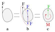
Fig. 8: A single force (a, black) is equivalent to a displaced force (c, green) and a displacement moment (c, red).
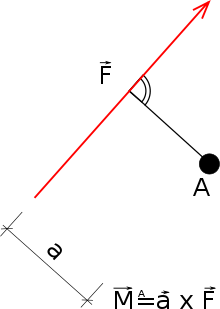
Force around a reference point
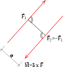
Force pair
Representations and notations
There are numerous notations for torques in equations and representations in drawings. If a plane in which the torque acts is shown in drawings, then it is usually represented by a curved arrow that can range between a quarter circle and a three-quarter circle. The tip then indicates the direction of rotation. In three-dimensional representations, arrows are used as three-quarter circles that rotate around specific axes or straight arrows that indicate the torque vectors. These can be represented by a simple arrow, as is generally the case with vectors. Since forces and torques occur simultaneously in many problems in mechanics, the torque vectors are also marked with a double point to avoid confusion.
Dependence on the reference point
For systems that are not in equilibrium, the value of the torque is generally dependent on the choice of the reference point. If the reference point is 

Here 

If the resulting force is zero, the body experiences no acceleration and the centre of gravity does not change its speed or direction of movement. The force causes only a change in angular momentum. In this case, the torque is independent of its reference point and can be moved freely without changing the effect on the bodies. Since this situation requires (at least) two forces that have the same magnitude 


Unit of measurement
The unit of measurement of torque in the SI is the Newton metre (Nm). With the basic units kilogram, metre and second, the following applies:
The unit of mechanical work is also the Newton metre and has the name "Joule" (1 J = 1 N-m). However, the unit name "joule" must not be used for torque, because torque and work are different physical quantities that cannot be converted into each other. Work is done when a force (component) acts parallel to a movement along a path. With torque, on the other hand, the force acts perpendicular to the distance formed by the lever arm. Work is a scalar quantity, whereas torque is a pseudo-vector.
The sentence "work = force times distance" corresponds here to "work = torque times angle". In order to illustrate this relationship, the torque can also be expressed as energy per angle using the unit "energy".
can be used, whereby the direction of the vector then points in the direction of the axis of rotation. Here 
In technical documents and on nameplates, torque is given in the unit Nm. Other units used are e.g. 
Addition of torques
Torques can be added to a resulting torque, similar to how forces can be added to a resulting force. If all torques are taken into account, one also speaks of the total torque. Relationships between the resultant force and the resultant torque are made by the moment theorem.
Total torque
The individual torques of two forces can be added if they refer to the same point
If there are any number of forces, the total torque is the sum of all torques. If they are referred to the origin, the result is

The vector 


Moment set of statics
The moment theorem of statics states that the moment of the resulting force 
The resulting force, which is formed from all existing forces, must have the same effect on a body as the individual forces. The vector addition of the individual forces results in the amount and direction of the resulting force, but neither its point of application nor its line of action. These are determined with the help of the law of moments. The resulting force must lie on the line of action on which it generates the same moment as the individual forces.
The moment theorem is particularly important for checking the moment equilibrium or for calculating unknown forces with the help of the moment equilibrium. Forces that lie at an angle to the coordinate axes in space can then be split into several forces that are perpendicular to the axes. Their moments can be calculated more easily. The moments caused by these force components correspond in sum to the moment caused by the original force.
Balance
When a body is in mechanical equilibrium, it does not change its state of motion. It is therefore neither accelerated nor decelerated.
If a body is in equilibrium, it is in equilibrium of forces as well as in equilibrium of torques or moments with respect to any point 
This applies to any point A and thus even to points that lie outside the body. A point suggests itself where the lines of action of as many forces as possible intersect. For these, the length of the lever arm is zero, which leads to a torque of zero. Consequently, these torques do not appear in the equation, which makes the calculation easier. If there is only one unknown force among these forces, it can be calculated directly. Sometimes it can be convenient to determine several torque equilibria if this allows a different unknown force to be calculated in each case.
If a body is in torque equilibrium with respect to one point, one cannot conclude from this that it is also in equilibrium as a whole, nor that it is in torque equilibrium with respect to other points. If, for example, only one force acts, it is in torque equilibrium with respect to a point on the line of action of this force, but not in torque equilibrium with respect to points off this line and also not in equilibrium as a whole, since a force acts for which there is no counterforce. However, a body is in equilibrium as a whole within a plane if it is in torque equilibrium with respect to three different points, provided these three points do not lie on a straight line.
Displacement of forces
A force arrow may be moved along its line of action without restriction without changing its action on a rigid body. In the position where the distance vector 
Force arm times force = load arm times load.
(Note that strictly speaking only the amounts are equal, because the two torques are opposite and therefore have different signs).
If a force is shifted perpendicular to its line of action by the distance 

Dynamics
→ Main article: Twist set
Dynamics deals with states that are not in equilibrium. According to Newton's 2nd law, a resulting external force on a body leads to a change in velocity (acceleration). Analogously, a resulting external torque means a change in angular velocity ω 


It should be noted here that the moment of inertia is not only dependent on the position of the axis of rotation (see Steiner's theorem), but also on its direction. If one wants to formulate the above equation more generally for any spatial direction, one must instead use the inertia tensor 
One can express the relationship between torque and rate of change of angular momentum ( 
In engineering mechanics, this equation is called the angular momentum theorem, momentum theorem or momentum-momentum theorem. (The angular momentum theorem also stands for the conservation of angular momentum theorem, the momentum theorem also stands for the momentum theorem from statics).
In the two-dimensional special case, a torque only causes an acceleration or deceleration of a rotational movement. In the general three-dimensional case, on the other hand, it can also change the direction of the rotation axis (see e.g.: precession).
Correspondences between rectilinear motion and rotary motion
The torque 

| Straight movement | Rotation | |
| Work | Force times displacement | Torque times angle of rotation (radian measure) |
| general: | general: | |
| Power | Force times velocity | Torque times angular velocity |
| Static balance | Equilibrium of forces | Torque equilibrium |
| Accelerated movement | Mass times acceleration | Inertia tensor times angular acceleration |
| Rate of change of the pulse | Rate of change of angular momentum |
- ↑ a b These simplified formulae apply to a constant force along a path in the direction of force or a constant torque about an axis in the direction of rotation. For variable forces and torques or for oblique arrangements, use the general formulae in the line below.
Torque measurement
See also: Torque sensor and torque transducer
Resting body
The rotatable body is held at rest by a static counter-torque. The torque acting on the body at rest and to be measured is the same as the counter-torque generated, for example, with a lever, the value of which is the product of the lever arm length and the counter-force at the end of the lever.
Rotating body
The torque acting on a rotating shaft at a certain speed is measured with a brake dynamometer, for example a Prony bridle or a water vortex brake. This braking device, which is connected to the shaft, absorbs the total transmitted power and measures the torque at the same time.
For example, a prime mover, on whose shaft the torque is to be measured, or the braking device are mounted rotatably about the axis of rotation of the shaft and the counteracting circumferential force is measured at the free end of a lever arm attached to the machine or to the braking device.
The measurement is repeated several times and a torque/speed characteristic curve is generated.
The torque changing the rotational speed can be 


Torques on selected machines
Electric motors
The asynchronous motor in the squirrel-cage rotor design is a frequently used electric motor. The figure shows the torque typically generated during operation on the mains (frequency and voltage constant) as a function of the speed. Over a longer period of time, the motor can only be operated in the small speed range to the right of the tipping points K1 or K2 on the steeply sloping curve. To the left of the tipping points is the start-up range, which must always be passed through as quickly as possible. During start-up, the asynchronous motor has a poor efficiency, a high starting current and a low torque. In order to avoid these disadvantages, various measures are taken, for example the star-delta starting circuit or operation with a frequency converter. By means of the latter, starting with more than the nominal torque is possible, so that the motor can also be used in vehicle drives.
Another frequently used motor is the series-wound DC motor, which has a particularly high starting torque. It is therefore used for hand-held appliances, washing machines or even train drives.
Internal combustion engines
In automotive brochures, it is common practice for internal combustion engines to state only their maximum value together with the corresponding speed instead of the torque/speed characteristic curve recorded in full-load operation (see figure "Characteristics of two internal combustion engines").
Since the equation for the power contains the speed again as a linear factor, the maximum of the power is at a higher speed than the maximum of the torque (see illustration).
For the torque 
Here 


The following applies accordingly to the torque of four-stroke engines:
Because with two revolutions per work cycle, the work per revolution is halved compared to the two-stroke.
Numerical example
Torque and power of a four-stroke engine
A production vehicle with 2000 cm³ (= 0.002 m³) displacement whose four-stroke engine reaches a mean pressure of 9 bar (= 900,000 Pa; 1 Pa = 1 N/m²) at a speed of 2000/min, calculated in SI units:
The equation for the power in a rotary motion is (see above; 
and as a function of the speed


An internal combustion engine that delivers 143 Nm of torque at 2000 rpm has the following power in this operating state:

Hydraulic motors
The hydraulic power 


From the equation for the power in a rotary motion (see above)
the torque increases:
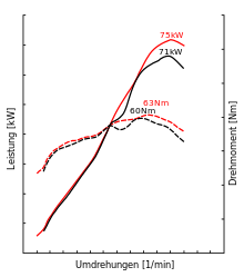
Characteristics of two combustion engines
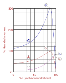
Torque characteristics of an asynchronous motor. Upper characteristic: Delta connectionMiddle characteristic: Star connection
Search within the encyclopedia


